A loading and unloading device for an annular heating furnace

A ring-shaped heating furnace and trolley technology, which is applied to lighting and heating equipment, furnaces, furnace components, etc., can solve problems such as the difficulty of completely controlling the furnace pressure of the heating furnace, the difficulty of long-term operation by the staff, and the rise in the temperature of the furnace mouth. Achieve the effect of improving effective space utilization, improving product quality, and reducing heating times

Active Publication Date: 2021-11-02
LUOYANG INST OF SCI & TECH
View PDF4 Cites 0 Cited by
  • Summary
  • Abstract
  • Description
  • Claims
  • Application Information

AI Technical Summary

Problems solved by technology

This kind of annular heating wheel loading and unloading device is still directly operated by the staff. On the one hand, because of manual direct operation, it is easy to cause bumps on the blanks grabbed by the manipulator, which affects product quality.
On the other hand, because the environment at the inlet and outlet of the annular heating furnace is very harsh, with high temperature and large dust, it is generally difficult for the staff to operate there for a long time, especially the operator of the loading and unloading machine at the furnace mouth. If the pressure in the furnace is not well controlled, it may cause the fire to run out, causing the temperature of the furnace mouth to rise sharply, and there may be a danger of scalding the operator. However, due to the limitations of current domestic and foreign technical capabilities, it is difficult to completely control it. The furnace pressure of the heating furnace, so the remote control and automatic control of the loading and unloading machine is a main direction of development today

Method used


Image

  • A loading and unloading device for an annular heating furnace
  • A loading and unloading device for an annular heating furnace
  • A loading and unloading device for an annular heating furnace

Examples


Embodiment Construction

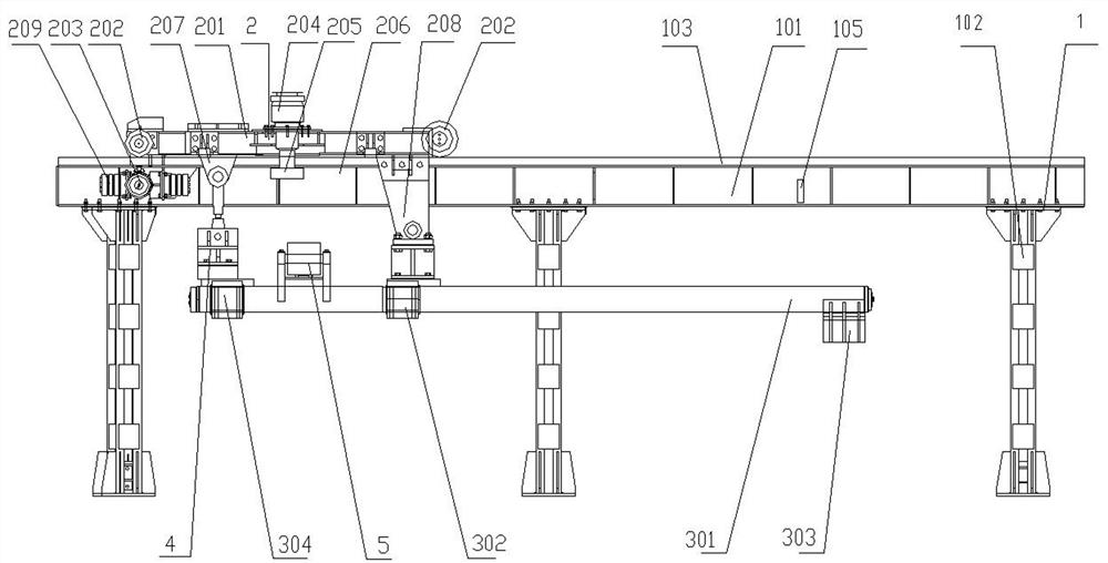
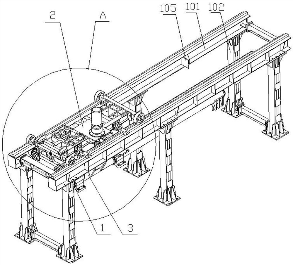
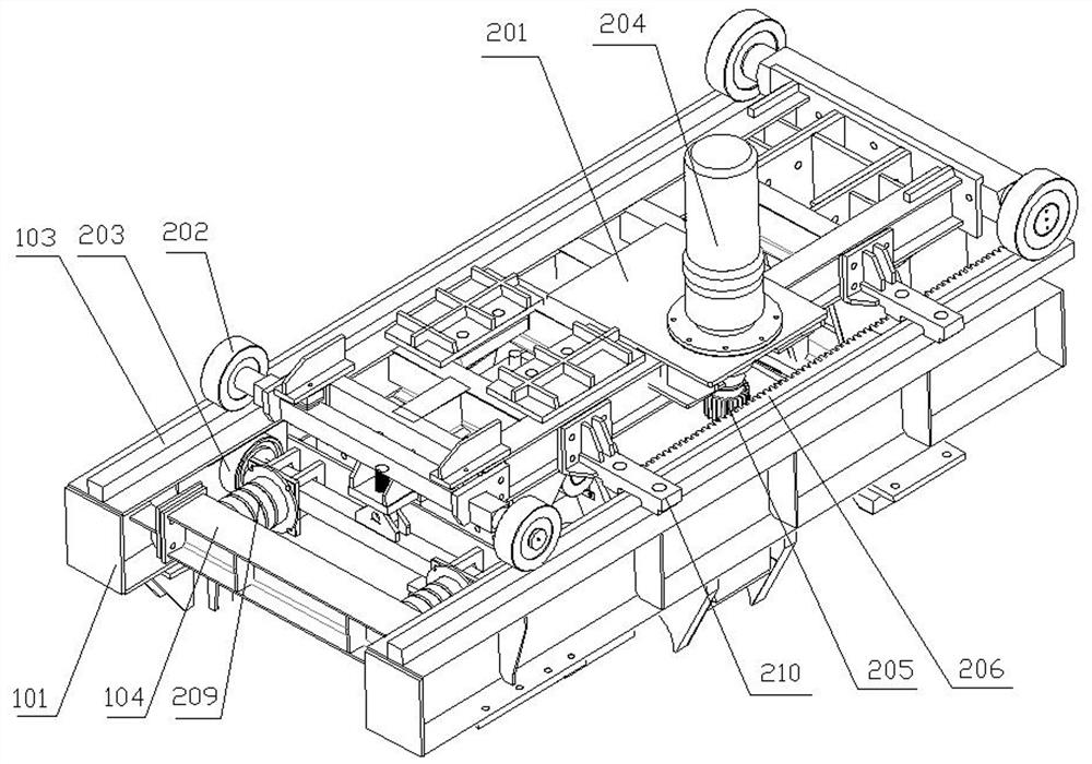
[0026] Such as Figure 1 to Figure 6 As shown, a loading and unloading device for an annular heating furnace of the present invention includes a frame 1 , a trolley 2 slidably arranged on the frame 1 , and a grabbing mechanism 3 disposed on the trolley 2 . The frame 1 is arranged at the loading and unloading port of the annular heating furnace, and the movement track of the trolley 2 is toward or away from the loading and unloading opening of the annular heating furnace. After grabbing the billet from the unloading rack by the gripping mechanism 3, the billet is put into the annular heating furnace with the sliding of the trolley 2 on the frame 1 and its own lifting, or taken out from the annular heating furnace.

[0027] The frame 1 includes two horizontal and parallel beams 101, the lower parts of the two beams 101 are respectively provided with three supporting columns 102 at even intervals, and the upper parts of the two beams 101 are provided along the length direction of...


PUM


Abstract

The invention relates to the field of steel processing equipment, in particular to a loading and unloading device for an annular heating furnace. It includes a frame, a trolley slidably set on the frame, and a grabbing mechanism set on the trolley; the grabbing mechanism includes two parallel clamp rods, and the middle parts of the two clamp rods are sleeved in the first double-hole bearing seat , the top of the first double-hole bearing seat is hinged with the bottom of the trolley, one end of the two clamp rods on the same side is respectively provided with a clamp opposite to the notch, and the other end is sleeved in the second double-hole bearing seat, the second There is a lifting cylinder between the double-hole bearing seat and the trolley. The telescopic end and the cylinder body end of the lifting cylinder are respectively hinged with the top of the second double-hole bearing seat and the bottom of the trolley. There is also a clamp between the two clamp rods. The telescoping end and the cylinder body end of the clamping cylinder are respectively hinged with swing arms, and the other ends of the two swing arms are respectively fixedly connected with two clamp rods. The invention can improve the automation degree of the feeding and discharging process of the annular heating furnace, and realize remote operation control.

Description

technical field [0001] The invention relates to the field of steel processing equipment, in particular to a loading and unloading device for an annular heating furnace. Background technique [0002] In the steel pipe manufacturing enterprise, to make the steel pipe shape, the steel pipe billet must be heated first, and then the steel pipe can be formed by the forming machine. Because the heating of the steel billet is different from that of other steel billets, the heating accuracy is very high, and all parts of the steel billet are required to be heated evenly, so as to prevent breakage, deformation, and uneven thickness distribution of the steel pipe during the drilling and straightening process. Uniformity, etc., so the traditional pusher type heating furnace cannot be used to heat it, because the heating of the traditional pusher type heating furnace is not very uniform. In the case of the traditional type, it is more heated in the middle, so the ring heating furnace ca...

Claims


Application Information

Patent Timeline
Patent Type & Authority Patents(China)
IPC IPC(8): F27D3/12
Inventor 李彬康红艳王红
Owner LUOYANG INST OF SCI & TECH
Why Eureka
Try Eureka