
Absolute position encoder combining signals of two widely separated wavelengths

An absolute position and encoder technology, applied in the direction of instruments, measuring devices, mechanical devices, etc., can solve problems such as resolution limitations and accuracy limitations

Active Publication Date: 2018-01-09
MITUTOYO CORP
View PDF22 Cites 2 Cited by
  • Summary
  • Abstract
  • Description
  • Claims
  • Application Information

AI Technical Summary

Problems solved by technology

However, especially in compact low-power encoders, using λ 1 and lambda 2 Certain accuracy limitations, resolution limitations, and / or range limitations may arise due to crosstalk errors and / or other difficulties in signal isolation

Method used


Image

  • Absolute position encoder combining signals of two widely separated wavelengths
  • Absolute position encoder combining signals of two widely separated wavelengths
  • Absolute position encoder combining signals of two widely separated wavelengths

Examples


Embodiment Construction

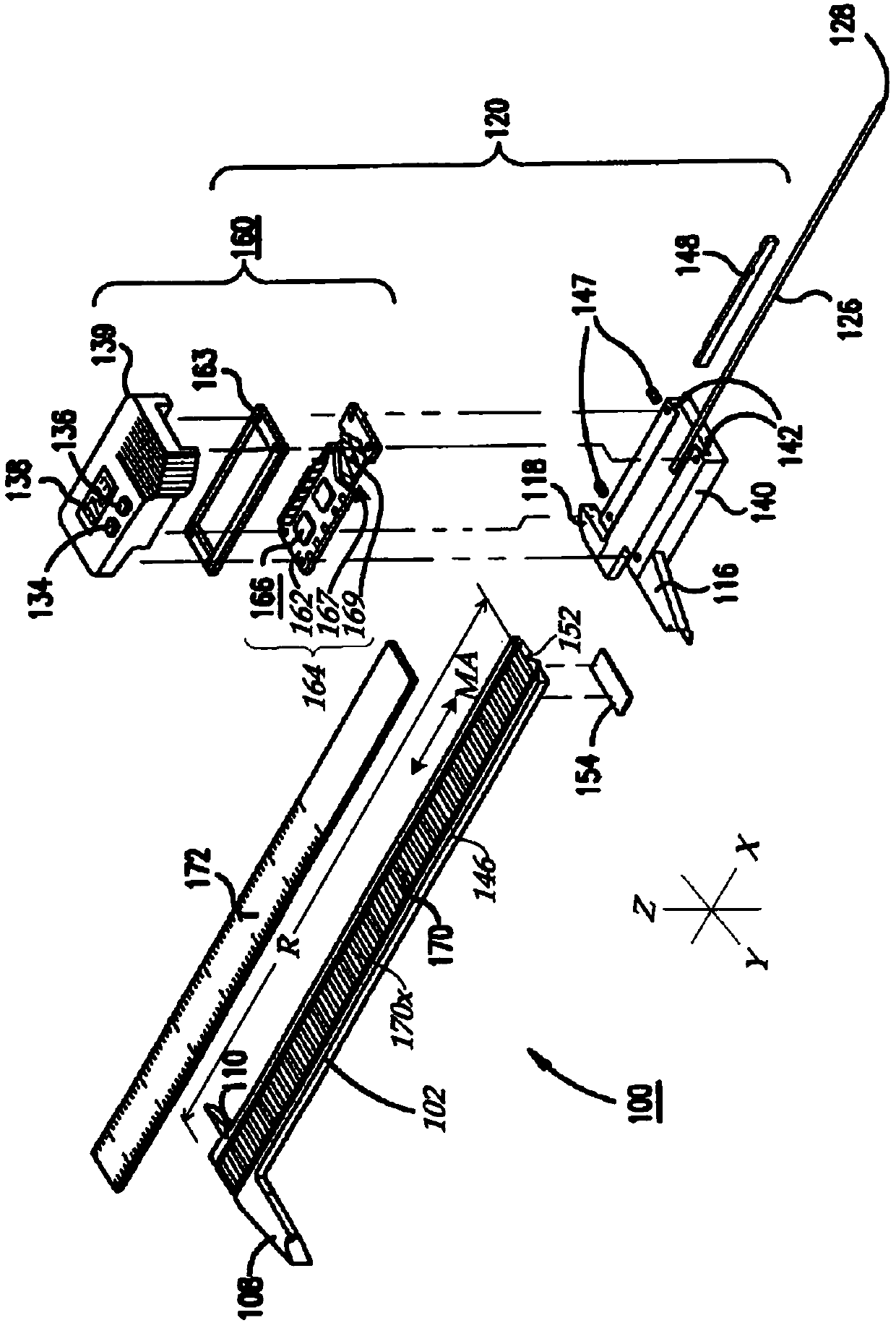
[0027] figure 1is an exploded isometric illustration of a hand tool type caliper 100 including a gauge member 102 having a generally rectangular cross-section spar including a gauge 170 and a slider assembly 120 . figure 1 X-Y-Z coordinate axes are shown for reference. The measurement axis direction is parallel to the X axis. The operation of these calipers is generally known, and calipers 100 are only briefly described here to indicate the various problems and / or problems that are expected to be addressed in creating an encoder design such as that disclosed herein. Some exemplary practical requirements for design constraints. Such as figure 1 As shown, the gauge 170 may include a (schematically represented) signal modulating gauge pattern 170x extending along the measurement axis direction MA (X-axis). The variable suffix "x" is replaced here by a different letter to designate a different corresponding signal modulation meter pattern. The signal modulating gauge pattern ...


PUM


Abstract

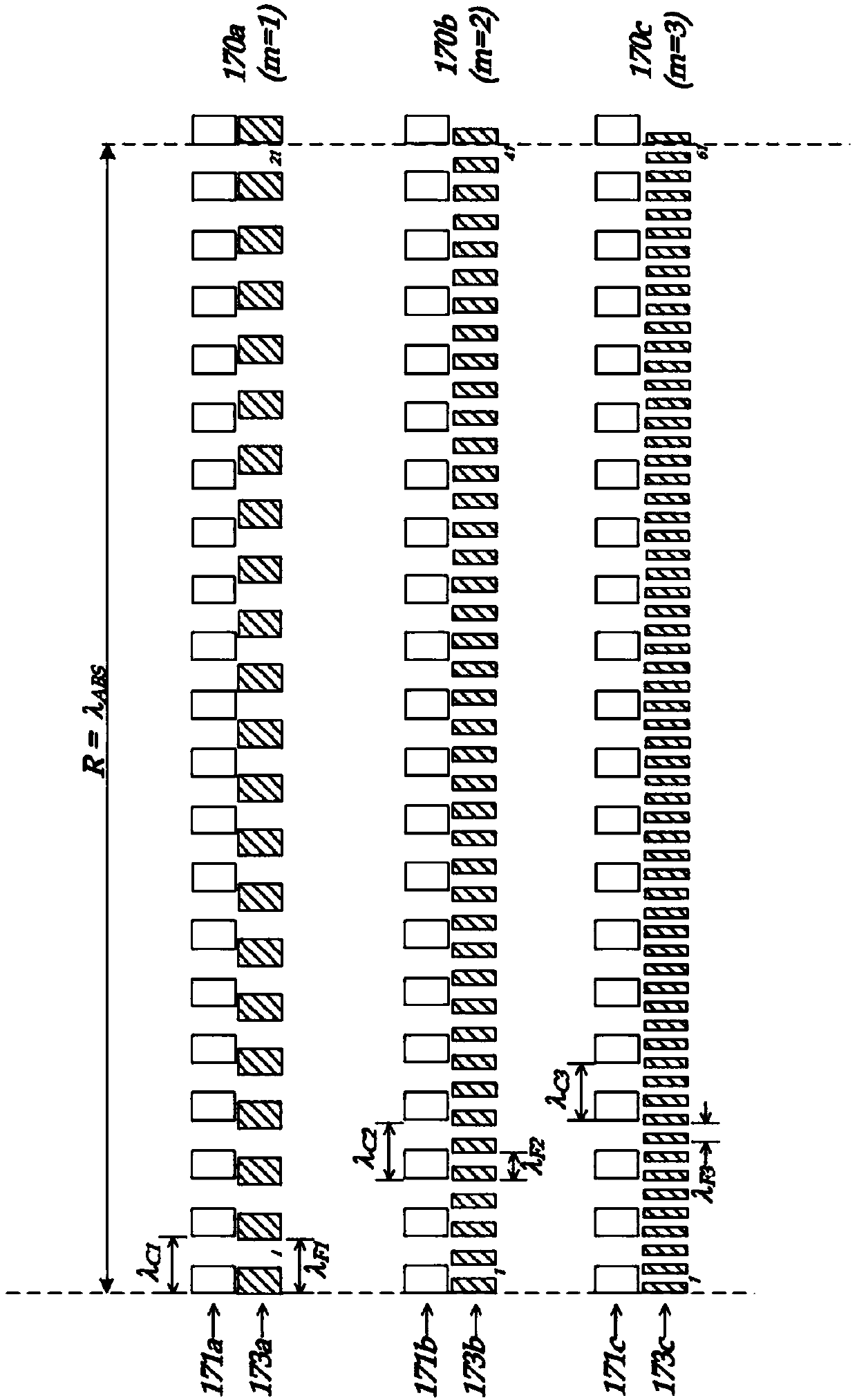
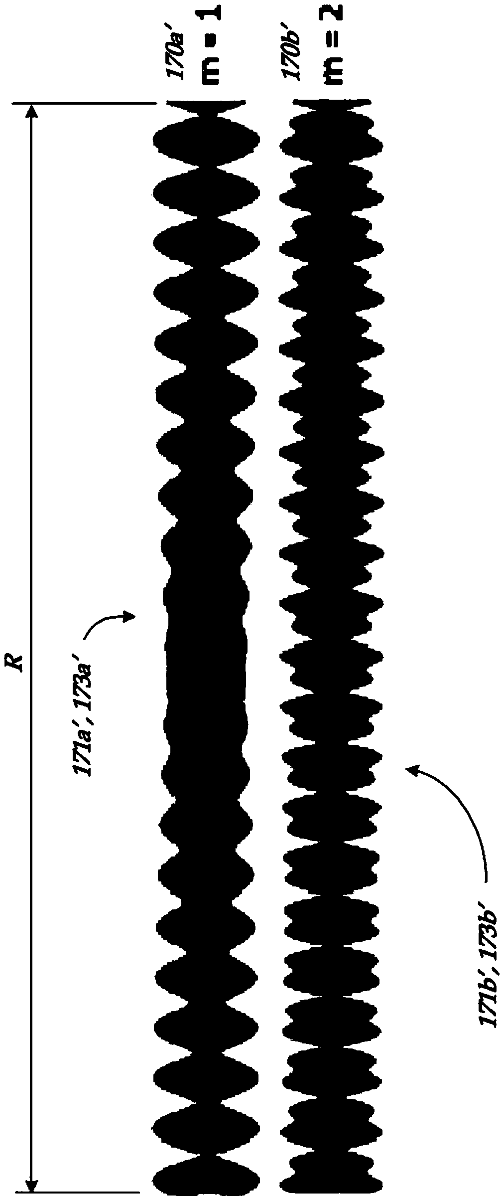
An electronic absolute position encoder includes a scale extending along a measuring axis direction (MA) and including a signal modulating scale pattern defining a corresponding absolute range R alongMA, a detector including sensing elements arranged along MA and configured to provide detector signals which respond to the signal modulating scale pattern, and a signal processing configuration thatdetermines an absolute position of the detector along the scale based on the detector signals. The signal modulating scale pattern includes a coarse periodic pattern component as a function of position along the scale having a spatial wavelength [lamda]C, wherein nx[lamda]C=R and n is an integer, and a fine periodic pattern component as a function of position along the scale having a spatial wavelength [lamda]F, wherein (mn+1)x[lamda]F=R and m is an integer that is at least two. The wavelengths [lamda]C and [lamda]C may be widely separated.

Description

technical field [0001] This invention relates generally to precision measuring instruments and, in particular, to absolute position encoders. Background technique [0002] Various optical, capacitive, electromagnetic and inductive transducers as well as movement or position transducers are available. These transducers use various geometric configurations of transmitters and receivers in the readhead to measure movement between the readhead and the gauge. Inductive sensors are known to be one of the most immune sensor types to contamination by particles, oil, water and other fluids. U.S. Patent No. 6,011,389 (the '389 patent) describes an inductive current position transducer usable in high precision applications, which is hereby incorporated by reference in its entirety. US Patent Nos. 5,973,494 and 6,002,250 describe incremental position sensing calipers and linear gauges including signal generation and processing circuits, which are hereby incorporated by reference in th...

Claims


Application Information

Patent Timeline
Patent Type & Authority Applications(China)
IPC IPC(8): G01D5/243
CPCG01B3/205G01D5/2006G01D5/2452G01D5/20
Inventor T.S.库克
Owner MITUTOYO CORP
Learn More