Automatic public charging system control method
A technology of a charging system and a control method, which is applied to electric vehicle charging technology, coin-operated equipment with instrument control, and current collectors, etc., can solve the problems of mobile phone user identification, manual connection of charging cables, and the need for people to be guarded. Achieve the effect of saving equipment costs, improving flexibility and convenience, and realizing intelligent access
- Summary
- Abstract
- Description
- Claims
- Application Information
AI Technical Summary
Problems solved by technology
Method used
Image
Examples
Embodiment 1
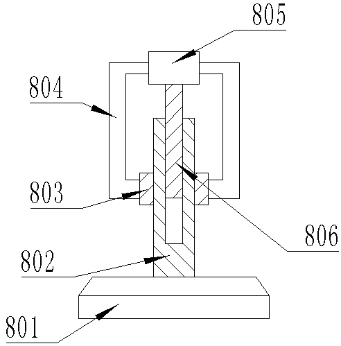
[0053] On the basis of the above embodiments, the present invention also discloses a preferred embodiment of automatic public charging equipment. The fixing device 8 includes a fixing arm 804, which is arranged on the charging slot 3, and a useful In the clamping motor 805 that provides power, the fixed arm 804 is provided with a guide ring 803, the guide ring 803 is movably connected with a fixed rod 802, one end of the fixed rod 802 is connected with a fixed claw 801, and the other end of the fixed rod 802 is threaded. hole, the rotating shaft of the clamping motor 805 is connected with a transmission rod 806, and the transmission rod 806 is matched with the threaded hole on the fixed rod 802 to be connected.
[0054] After the charging device is put into the charging slot 3, the clamping motor 805 rotates and drives the transmission rod 806 to rotate. The transmission rod 806 is provided with threads, and the transmission rod 806 is connected with the threaded hole on the fi...
Embodiment 2
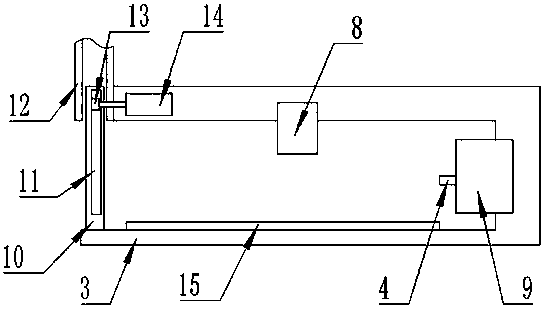
[0057] On the basis of Example 1, the present invention also discloses a preferred implementation of automated public charging equipment. The positioning device 9 includes horizontally arranged horizontal rails 901. The horizontal rails 901 are arranged on the charging slot 3. The horizontal rails 901 A vertical rail 902 is movably connected to the upper side, and a slider 904 is movably connected to the vertical rail 902 , and a charging plug 4 is arranged on the slider 904 ; a camera 903 is also arranged in the charging tank 3 .
[0058] Further, the slider 904 includes a chute 906, a slide bar 907 is connected to the power in the chute 906, and one end of the slide bar 907 is provided with a swivel head 905, and the swivel head 905 is connected with the charging plug 4; The vertical rails 902 are connected through a power mechanism, and the vertical rails 902 and the slider 904 are connected through a power mechanism.
[0059] The vertical rail 902 can drive the slider 904 ...
Embodiment 3
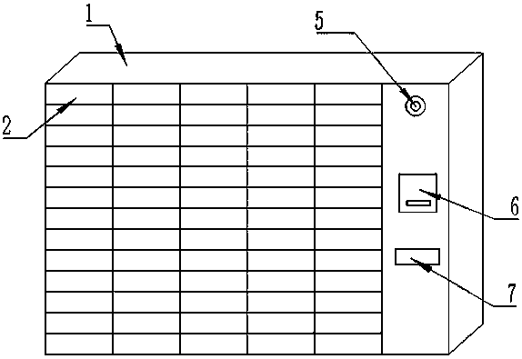
[0061] On the basis of Embodiment 1 or 2, the control circuit includes a charging circuit, the charging circuit is connected to the central control unit through a communication interface, and the charging circuit is electrically connected to the charging line 4 through a cable; the interface of the charging line 4 includes a Micro USB interface , a USB Type C interface and a Lightning interface; the charging grid 2 and the charging slot 3 match each other, and the charging grid 2 on the charging cabinet 1 has various specifications, which can accommodate electronic devices of different sizes and structures for charging.
[0062] The charging circuit can provide electric energy for the electronic equipment, and the central control unit can adjust the charging mode and the charging current according to the type of the electronic equipment and the input equipment, so as to achieve the maximum charging effect and ensure the charging efficiency. Micro USB interface, USB Type C inter...
PUM
 Abstract
Description
Claims
Application Information
 - R&D
- Intellectual Property
- Life Sciences
- Materials
- Tech Scout
- Unparalleled Data Quality
- Higher Quality Content
- 60% Fewer Hallucinations
Browse by: Latest US Patents, China's latest patents, Technical Efficacy Thesaurus, Application Domain, Technology Topic, Popular Technical Reports.
© 2025 PatSnap. All rights reserved.Legal|Privacy policy|Modern Slavery Act Transparency Statement|Sitemap|About US| Contact US: help@patsnap.com


