
Motor wire end and outgoing wire twisting device

A technology of lead-out wires and thread ends, which is applied in the direction of electromechanical devices, manufacturing motor generators, electrical components, etc., can solve the problems of low degree of automation, slow speed of lead-out wires, unfavorable twisting of wires, etc., and achieve enhanced safety, good stability, Ease of use

Pending Publication Date: 2018-01-09
UNIV OF ELECTRONICS SCI & TECH OF CHINA ZHONGSHAN INST
View PDF9 Cites 0 Cited by
  • Summary
  • Abstract
  • Description
  • Claims
  • Application Information

AI Technical Summary

Problems solved by technology

[0002] The application field of the motor is more and more extensive. The motor with 6 lead wires leads out the head and the tail of the three-phase winding of the motor separately, which is convenient for some motors to facilitate wiring when starting. The motor with only three lead wires is The three windings of the motor are connected internally according to the established connection method when the motor is manufactured, and only three lead-out wires are drawn out, and the coil is an indispensable part of the motor. As a major producer of motors, the current degree of automation of motor production in my country Low, most of the existing domestic motor production equipment is semi-automatic manual operation, twisting and breaking wires are more purely manual operations, resulting in relatively low work efficiency, high product defect rate, and high production costs, so it is necessary To further improve the existing motor production methods and equipment
[0003] The wire twisting device in the prior art does not have a protective function, and the operation safety is lacking. Impurities can easily fall on the lead-out wire and affect the conduction of the line. The next time you twist the wires, the wire twisting device in the prior art cannot effectively keep the lead-out wires in a straight state, resulting in loose twisted wires and affecting product quality, so there is an urgent need for a motor thread and lead-out wire twisting device to solve the above problems The problem

Method used


Image

  • Motor wire end and outgoing wire twisting device
  • Motor wire end and outgoing wire twisting device
  • Motor wire end and outgoing wire twisting device

Examples


Embodiment Construction

[0021] In order to make the technical means, creative features, goals and effects achieved by the present invention easy to understand, the present invention will be further described below in conjunction with specific embodiments.

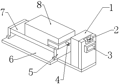
[0022] see Figure 1-Figure 4 , the present invention provides a technical solution: a motor thread head and lead wire twisting device, including a device main body, a protection mechanism 1, a thread cutting mechanism 2 and an adjustment mechanism 3, and the device main body includes a thread twisting manipulator 4, a support plate 5, and a base 6 , the mounting plate 7 and the control box 8, the twisting manipulator 4 is installed on the right end face of the control box 8, the support plate 5 is installed on the left end and the right end of the upper end face of the base 6, the mounting plate 7 is welded on the upper end face of the support plate 5, and the control box 8 is installed on the The upper end face of the mounting plate 7.

[0023]...


PUM


Abstract

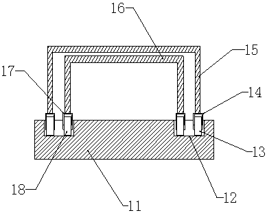
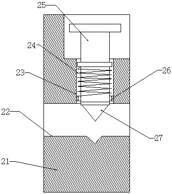
The invention provides a motor wire end and outgoing wire twisting device, comprising rollers I, frame plate I, frame plate II, rollers II, a press rod, a cutter head, round-orifice posts, positioningbolts and pulleys. The motor wire end and outgoing wire twisting device has the advantages that the frame plate I is connected with the rollers I through mounting racks I, the frame plate II is connected with the rollers II through mounting racks II, a protective function is provided for wire twisting operation, and operational safety is enhanced; the press rod is arranged in a mounting hole, thecutter head is mounted on the lower end face of the press rod, a quick cutting function is provided for outgoing wires, cuts are neat, and next wire twisting is facilitated; the positioning bolts aremounted on the round-orifice posts, the pulleys are mounted in the round-orifice posts, a tension adjusting function is provided for the outgoing wires, and it is ensured that the outgoing wires aretensioned during twisting; the motor wire end and outgoing wire twisting device is convenient to use and operate, good in stability, and high in reliability.

Description

technical field [0001] The invention relates to a motor thread head and lead wire twisting device, which belongs to the field of motor production and processing equipment. Background technique [0002] The application field of the motor is more and more extensive. The motor with 6 lead wires leads out the head and the tail of the three-phase winding of the motor separately, which is convenient for some motors to facilitate wiring when starting. The motor with only three lead wires is The three windings of the motor are connected internally according to the established connection method when the motor is manufactured, and only three lead-out wires are drawn out, and the coil is an indispensable part of the motor. As a major producer of motors, the current degree of automation of motor production in my country Low, most of the existing domestic motor production equipment is semi-automatic manual operation, twisting and breaking wires are more purely manual operations, resulting ...

Claims


Application Information

Patent Timeline
Patent Type & Authority Applications(China)
IPC IPC(8): H02K15/00
Inventor 杨亮石世光
Owner UNIV OF ELECTRONICS SCI & TECH OF CHINA ZHONGSHAN INST
Learn More