Automatic soldering iron device

An automatic welding and soldering iron technology, applied in the direction of soldering irons, welding equipment, metal processing equipment, etc., can solve the problems of inability to realize welding and cutting, inability to realize fast welding, and high uncertainty coefficient, so as to improve welding efficiency, improve welding quality, The effect of convenient welding operation

Inactive Publication Date: 2018-01-12
SHANGHAI INST OF TECH
View PDF7 Cites 3 Cited by
  • Summary
  • Abstract
  • Description
  • Claims
  • Application Information

AI Technical Summary

Problems solved by technology

Due to the temporary positioning of electronic components during the welding process, the operator needs to free up one hand to position the components. Usually, a soldering iron bracket needs to be installed next to the welding station to facilitate the placement of the soldering iron at any time. The efficiency is low, and the position of the solder wire is a manual groove line, the uncertainty coefficient is high, resulting in low welding quality
When soldering electronic components in large quantities, it is necessary to design and manufacture special tooling for fixing the circuit board, and usually after the soldered material on the circuit board is welded, it is necessary to use scissors to trim the excess part of the soldered material, which cannot achieve integrated welding The cutting function cannot realize fast welding, and the welding efficiency is low

Method used


Image

  • Automatic soldering iron device
  • Automatic soldering iron device
  • Automatic soldering iron device

Examples


Embodiment Construction

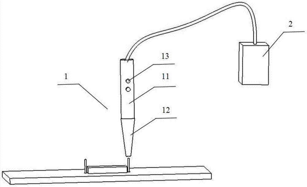
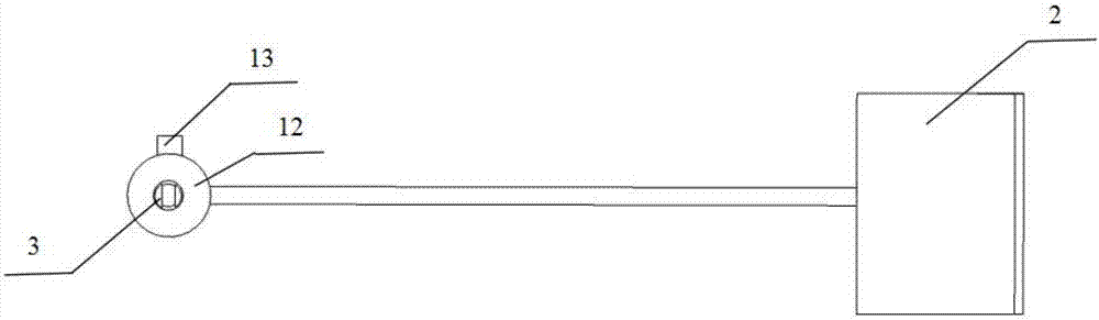
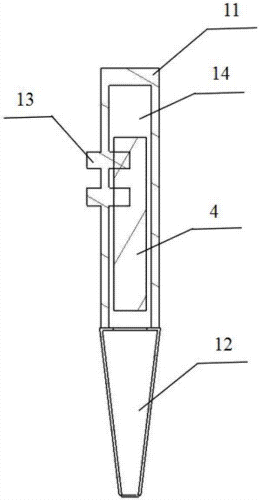
[0024] like figure 1 , 2 As shown in and 3, an automatic soldering iron device 1 includes an external power supply device 2, a hand-held part 11, and a welding head 12 connected to the lower end of the hand-held part 11. The welding end of the welding head 12 is provided with a The heating device of the material, the heating device is a ring-shaped heating wire, the middle of the hand-held part 11 is a cavity structure 14, and also includes a solder block 4 arranged inside the cavity structure 14, and arranged in the cavity structure 14. The cutting device 3 at the bottom of the welding end of the welding head 12 also includes a pushing device arranged inside the cavity structure 14, and also includes a control device 13 arranged on the handle 11, and the control device 13 is connected to the The heating device, the cutting device 3 and the pushing device are all electrically connected. like figure 2 As shown, the cutting device 3 is two blades symmetrically arranged in a ...


PUM


Abstract

The invention discloses an automatic soldering iron device. The automatic soldering iron device comprises a power supply device, a handheld part and a welding head connected with the lower end of thehandheld part. A heating device used for melting iron materials is arranged at the welding end of the welding head. The middle portion of the handheld part is of a cavity structure. The automatic soldering iron device further comprises a soldering tin block, a cutting device and a pushing device, wherein the soldering tin block is arranged in the cavity structure, the cutting device is arranged atthe bottom of the welding end of the welding head, and the pushing device is arranged in the cavity structure. The lower end of the handheld part is rotatably connected with the welding head in a buckled mode. According to the automatic soldering iron device, the welding head is inserted into a to-be-welded object, welding work can be completed by a worker with a single hand, rapid welding can beachieved, and meanwhile, the problem of cutting-off of redundant weld materials is solved.

Description

technical field [0001] The invention relates to the technical field of welding of electronic components, in particular to an automatic soldering iron device. Background technique [0002] The conventional tool in the circuit board welding technology is a soldering iron and a solder wire used together. The operator holds the soldering iron in one hand and aims at the object to be welded, and the other hand continuously feeds the soldering wire into the welding tip of the soldering iron. Complete the soldering work on the object to be soldered on the circuit board. Due to the temporary positioning of electronic components during the welding process, the operator needs to free up one hand to position the components. Usually, a soldering iron bracket needs to be installed next to the welding station to facilitate the placement of the soldering iron at any time. The efficiency is low, and the position of the solder wire is a manual groove line, the uncertainty coefficient is hig...

Claims


Application Information

Patent Timeline
Patent Type & Authority Applications(China)
IPC IPC(8): B23K3/02
Inventor 杨晨舸王文卿魏祎凡钱平
Owner SHANGHAI INST OF TECH
Why Eureka
Try Eureka