
A kind of welding method of gripper shell

A welding method and shell technology, which is applied in the field of projectile shell welding, can solve the problems of high scrap rate, difficulty in controlling the shape of the inner hole, consistent shape of ferrules, etc., achieve low welding process requirements, and reduce welding technical requirements , The effect of reducing processing costs

Active Publication Date: 2020-01-10
NANTONG UNIVERSITY
View PDF6 Cites 0 Cited by
  • Summary
  • Abstract
  • Description
  • Claims
  • Application Information

AI Technical Summary

Problems solved by technology

There are two disadvantages in this method: one is that the inner wall of the semi-finished product is not smooth due to the use of a drill bit to drill the blind hole, and there are obvious drill lines, which is difficult to handle. big error
[0005] Second, the blind hole drilled by the drill bit is pressed into a rectangular hole through the ferrule. The repeated pressing process can easily cause cracks in the material, resulting in a high rate of defective products; and due to the rigidity of the material itself, the inner hole cannot be matched with the insert The shape of the core is exactly the same, especially the shape of the corner of the rectangle is difficult to control
[0008] The welding method avoids the shortcomings of the inner wall being not smooth and the bottom of the blind hole not being flat caused by the drilling method, but it still has the disadvantages of high scrap rate during the pressing process and difficulty in controlling the shape of the inner hole
In addition, because the shuttle head of the projectile housing is made of surfacing welding, the internal structure of the surfacing part is not uniform, and air bubbles will be generated inside and on the surface, and its strength and rigidity are not as good as the shuttle head of the projectile housing formed by the drilling method.

Method used


Image

  • A kind of welding method of gripper shell
  • A kind of welding method of gripper shell

Examples


Embodiment Construction

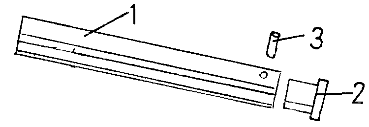
[0022] A welding method for a gripper case, the gripper case includes a shuttle body 1 and a shuttle head 2; the shuttle head has a stepped structure, the small end of the stepped structure is inserted into the shuttle body, and the large end of the stepped structure The inner end surface is in contact with the end surface of the shuttle body, and the small end is provided with a pin hole; the shuttle body is provided with a pin hole matching with the pin hole on the shuttle head; the pin 3 is inserted in the pin hole to connect the shuttle head and the shuttle body Integrate; the shuttle body and the shuttle head are also connected by high-frequency pressure welding; including the following steps:

[0023] (1) Clean up the welding contact surface and add solder pieces on the welding contact surface;

[0024] (2) Assemble the shuttle body, shuttle head and pin into one;

[0025] (3) The shuttle body and the shuttle head are welded by high-frequency welding method;

[0026] (...


PUM


Abstract

The invention discloses a method for welding gripper shuttle shells. The method includes steps of (1), cleaning welding contact surfaces and adding welding flakes to the welding contact surfaces; (2),integrally assembling shuttle bodies, shuttle heads and pins with one another; (3), welding the shuttle bodies and the shuttle heads by the aid of high-frequency welding processes; (4), carrying outstamping molding on welded portions while the welded portions are in high-temperature states and stamping welded ends to obtain welded ends in the shapes of cambered surfaces; (5), placing the weldedgripper shuttle shells in heat preservation tanks and preserving heat. The method has the advantages that the heads of the gripper shuttle shells can be assuredly free of crack or bubble, and loose-weld breakage and retracted head conditions can be prevented in service procedures; structures are simple, the method is reliable in quality and low in cost and has low requirements on welding processes.

Description

technical field [0001] The invention relates to a welding method for a gripper case. Background technique [0002] The projectile loom uses projectile weft insertion, and the projectile is half-holding the weft yarn. By changing the clamping force of the projectile, weaving of different types of fabrics can be completed. The projectile is composed of two parts, the bobbin case and the yarn clamp. The braking surface of the bobbin case is designed as a plane to ensure the flight and braking stability of the projectile. The bobbin case needs to be hardened to improve its wear resistance and knock resistance. [0003] At present, our country mainly adopts two processing methods of drilling and welding. [0004] (1) Drilling method: The drilling method is represented by Suzhou Lide Textile Machinery Co., Ltd., and its main process steps are as follows: (1) Drilling for blanking: according to the length, hole depth and cross-sectional area of ​​the gripper shell. Long bar stoc...

Claims


Application Information

Patent Timeline
Patent Type & Authority Patents(China)
IPC IPC(8): B23P15/00
CPCB23P15/00
Inventor 肖坤楠金路锋陈燕云瞿静郭东军肖龙雪肖镂盛张敏
Owner NANTONG UNIVERSITY
Learn More