Eureka AIR delivers breakthrough ideas for toughest innovation challenges, trusted by R&D personnel around the world.

Tertiary filtration-circulation system for cutting fluid of machine tool during machining

A three-stage filtration and circulation system technology, which is applied to metal processing machinery parts, metal processing equipment, manufacturing tools, etc., can solve the problems that affect the production efficiency of machine tools, frequent cleaning of pipeline filters, etc., and achieve the effect of convenient cleaning

Pending Publication Date: 2018-01-12
上海浦东同乐志刚机床附件有限公司
View PDF6 Cites 6 Cited by
  • Summary
  • Abstract
  • Description
  • Claims
  • Application Information

AI Technical Summary

Problems solved by technology

In the past, the chip removal and filtration cycle of the machine tool can only achieve two-level filtration, and usually the first-level filtration can only reach a filtration accuracy of 1000μ, and the second-level filter is forced to achieve a filtration accuracy of 40-50μ through a single-barrel pipeline filter, which leads to The consequence is that the pipeline filter of a single barrel is cleaned frequently, and the cleaning of the pipeline filter of a single barrel must stop the operation of the entire system, which seriously affects the production efficiency of the machine tool

Method used


Image

  • Tertiary filtration-circulation system for cutting fluid of machine tool during machining
  • Tertiary filtration-circulation system for cutting fluid of machine tool during machining

Examples


Embodiment Construction

[0015] The specific embodiments of the present invention will be further described below in conjunction with the accompanying drawings.

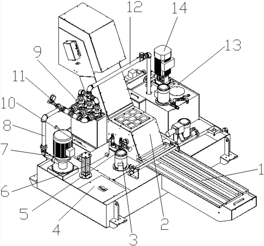
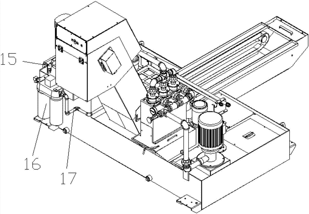
[0016] like figure 1 and 2 As shown, a three-stage filtration circulation system for cutting fluid of a processing machine tool according to the present invention includes a machine body, a scraper chip removal device is provided on the body, and a driving motor for driving the scraper chip removal device, and the front side of the body is provided with Dirty liquid tank 1, a scraper chip removal device is arranged in the dirty liquid tank 1, a recoil drum filter 2 is provided on the rear side of the dirty liquid tank 1, and a filter outlet side of the recoil drum filter 2 is provided with A buffer box 4, the side of the buffer box 4 close to the recoil drum filter 2 is provided with a recoil pump 3, and the water outlet of the recoil pump 3 is arranged on one side of the drum of the recoil drum filter 2, the The buffer box 4 is also provi...


PUM


Abstract

The invention discloses a tertiary filtration-circulation system for a cutting fluid of a machine tool during machining. The tertiary filtration-circulation system comprises an engine body, wherein adirty fluid bath is arranged on the front side of the machine body; a scraper chip-removal device is arranged in the dirty fluid bath; a backflush drum filter is arranged on the rear side of the dirtyfluid bath; a buffer box is arranged on the side of the filtration water outlet of the backflush drum filter; a backflush pump is arranged on the side, close to the backflush drum filter, of the buffer box; the water outlet of the backflush pump is arranged on the side of the drum of the backflush drum filter; a lift pump is also arranged on the buffer box; a series vortex device is connected with the lift pump through a pipeline I; a dirt collection box is arranged at the bottom of the series vortex device; a fluid purification box is connected with the water outlet of the series vortex device through a pipeline II; an internal cooling pump is arranged on the fluid purification box; and a double-bucket pipeline filter is connected with the water outlet of the internal cooling pump through a pipeline III. Compared with a conventional chip removal machine, a chip removal machine tertiary filtration system, namely the tertiary filtration-circulation system disclosed by the invention, has the advantages that fine particles in the cutting fluid can be further filtered out; furthermore, the continuous filtration can be achieved without halting the machine tool and cleaning the filters,and accordingly, the production efficiency of the machine tool can be improved.

Description

technical field [0001] The invention relates to a cutting fluid filtering system, in particular to a three-stage filtering circulation system for cutting fluid of a processing machine tool. Background technique [0002] During the machining process, the machine tool needs to use cutting fluid to lubricate and cool the cutting tool and workpiece. Since a large amount of cutting chips will be mixed into the cutting fluid during the machining process of the machine tool, the cutting fluid must be filtered before it can be recycled. In the past, the chip removal and filtration cycle of the machine tool can only achieve two-level filtration, and usually the first-level filtration can only reach a filtration accuracy of 1000μ, and the second-level filter is forced to achieve a filtration accuracy of 40-50μ through a single-barrel pipeline filter, which leads to The result is that the pipeline filter of a single barrel is cleaned frequently, and the operation of the entire system ...

Claims


Application Information

Patent Timeline
IPC IPC(8): B23Q11/10
Inventor 丁维倪文杰
Owner 上海浦东同乐志刚机床附件有限公司
Why Eureka
Eureka Blog
Learn More