Bottle cap feeding and spraying production machine

A technology for production machinery and spraying mechanism, applied in conveyors, spraying devices, conveyor objects, etc., can solve problems such as low production efficiency, and achieve the effect of improving production efficiency and improving screening efficiency

Inactive Publication Date: 2018-01-12
浙江金诺热工科技有限公司
View PDF1 Cites 1 Cited by
  • Summary
  • Abstract
  • Description
  • Claims
  • Application Information

AI Technical Summary

Problems solved by technology

[0005] The purpose of the present invention is to address the shortcomings of the prior art and provide a bottle cap feeding and spraying production machine. After the bottle caps are arranged in an orderly manner through the vibrating plate, the bottle caps are screened by the screening component, and then combined with the spraying mechanism. The material component carries out the orderly and efficient feeding of bottle caps, which solves the technical problem of low production efficiency of automatic feeding of bottle caps existing in the prior art

Method used


Image

  • Bottle cap feeding and spraying production machine
  • Bottle cap feeding and spraying production machine
  • Bottle cap feeding and spraying production machine

Examples


Embodiment 1

[0044] Embodiments of the present invention are described in detail below, examples of which are shown in the drawings, wherein the same or similar reference numerals designate the same or similar elements or elements having the same or similar functions throughout. The embodiments described below by referring to the figures are exemplary and are intended to explain the present invention and should not be construed as limiting the present invention.

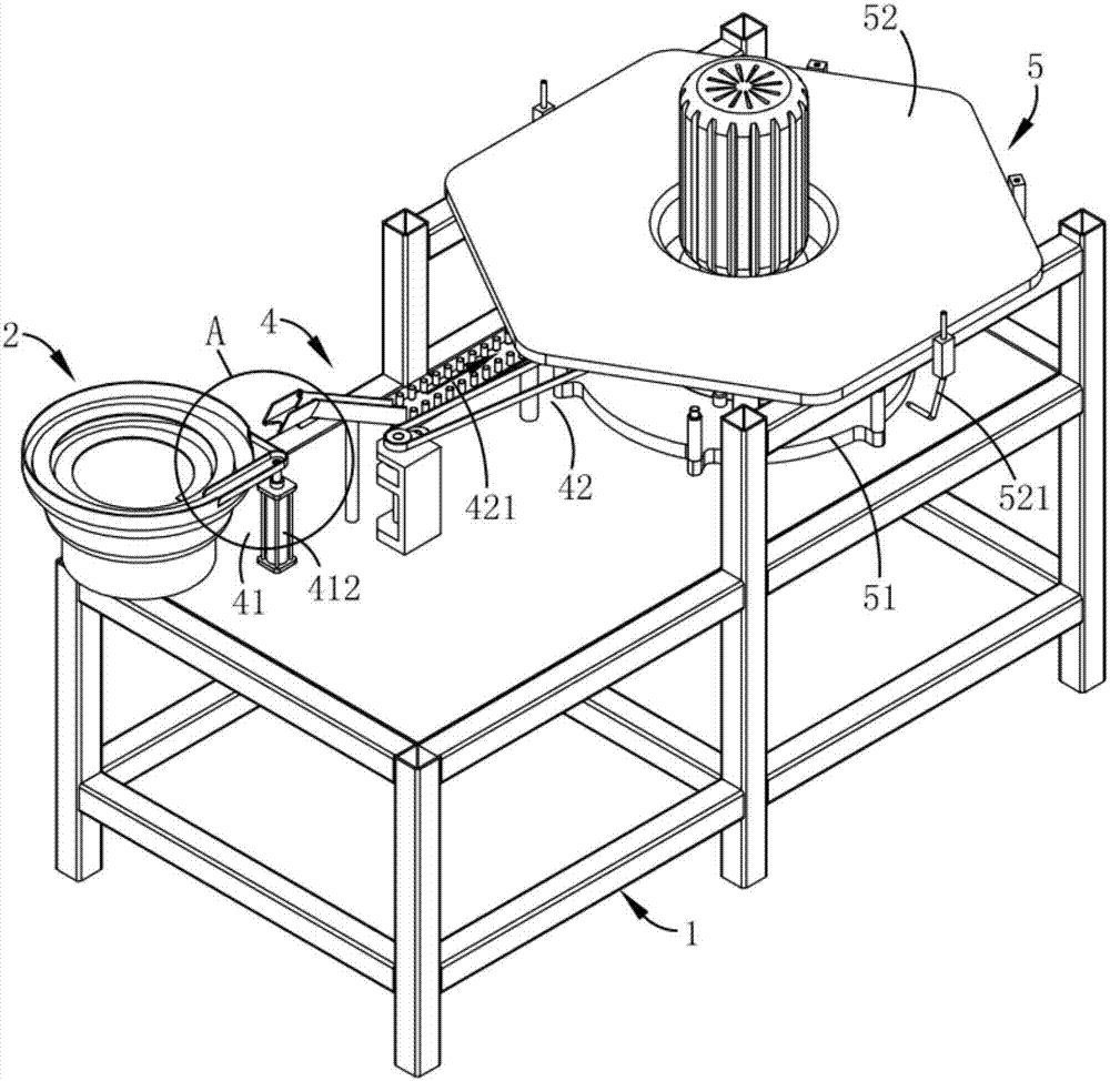
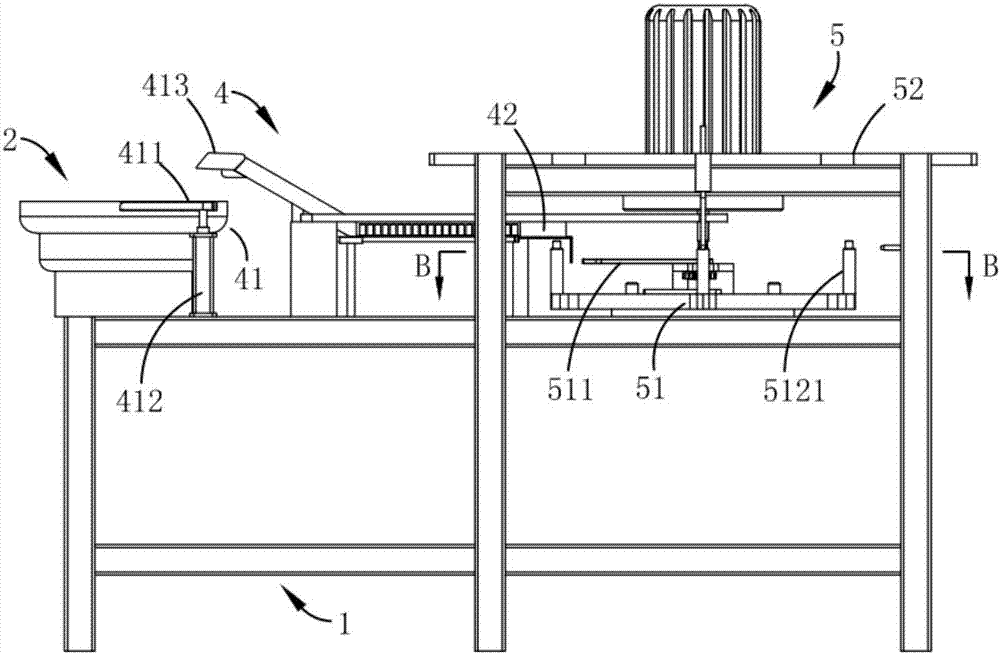
[0045] Such as figure 1 and 2 As shown, a bottle cap feeding and spraying production machine includes a frame 1 and a vibrating plate 2 for linearly sorting and transporting bottle caps, and is characterized in that it also includes:

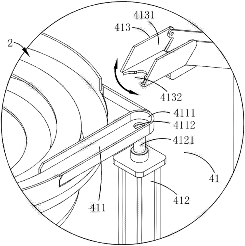
[0046] Feeding mechanism 4, described feeding mechanism 4 is installed on the described frame 1, and it comprises the screening component 41 that is arranged on the vibrating plate 2 to carry out the bottle cap screening and the bottle cap after screening is sprayed and loaded. material assembly ...

Embodiment 2

[0059] Such as figure 1 and 2 As shown, the parts that are the same as or corresponding to those in Embodiment 1 adopt the reference numerals corresponding to Embodiment 2. For the sake of simplicity, only the differences between Embodiment 1 and Embodiment 1 are described below; the differences between Embodiment 2 and Embodiment 1 The difference is that the spraying mechanism 5 also includes a spraying assembly 52 arranged above the station conversion assembly 51 for multi-station intermittent spraying of bottle caps, and the spraying assembly 52 is arranged in cooperation with the station conversion assembly 51 .

[0060] Among them, such as Figure 11 and 12 As shown, the station conversion assembly 51 includes a station turntable 512 which is rotatably arranged on the frame 1 and a second driving part 513 which drives the station turntable 512 to drive the bottle cap to carry out station transfer; wherein the station turntable 512 has a certain damping setting, and the...


PUM


Abstract

The invention relates to a bottle cap feeding and spraying production machine. The bottle cap feeding and spraying production machine comprises a rack, a vibrating disc, a feeding mechanism and a spraying mechanism, and the feeding mechanism is installed on the rack and comprises a screening assembly arranged on the vibrating disc and used for conducting bottle cap screening and a feeding assemblyconducting spraying and feeding on screened bottle caps; the spraying mechanism comprises a station conversion assembly used for bottle cap station transferring in a rotary motion manner and a firstdriving part arranged on the station conversion assembly, the first driving part is in transmission connection with the feeding assembly in the working process, and one-by-one feeding of the bottle caps is carried out; and after the bottle caps are arranged in order through the vibrating disc, bottle cap screening is carried out with the screening assembly, the spraying mechanism is combined withthe feeding assembly to conduct in-order and efficient feeding of the bottle caps, and the technical problem that the automatic bottle cap feeding production efficiency is low in the prior art is solved.

Description

technical field [0001] The invention belongs to the field of bottle cap spraying equipment, in particular to a bottle cap feeding and spraying production machine. Background technique [0002] The production process of the injection molding cap is roughly the same as that of the compression molding cap. The mixed material is put into the barrel of the injection molding machine, and after being melted at high temperature, it is injected into the mold cavity for cooling and shaping. At the same time, in order to improve the aesthetics of wine bottle caps, spraying is usually required in the production process; with the rapid development of modern technology and the improvement of people's living standards, the visual effect of product colors is increasing day by day. To improve the visual appeal of products to customers, various manufacturers use the color matching of bottle caps to achieve the purpose of attracting customers; when multi-color spraying is performed on bottle c...

Claims


Application Information

Patent Timeline
Patent Type & Authority Applications(China)
IPC IPC(8): B65G27/02B65G47/26B65G47/256B05B13/02
Inventor 吴立荣李乔宝王德祥
Owner 浙江金诺热工科技有限公司
Why Eureka
Try Eureka