[0021] The present invention will be described in further detail below in conjunction with the accompanying drawings.
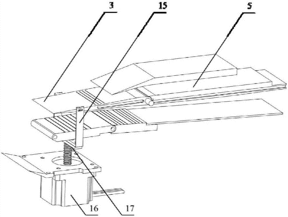
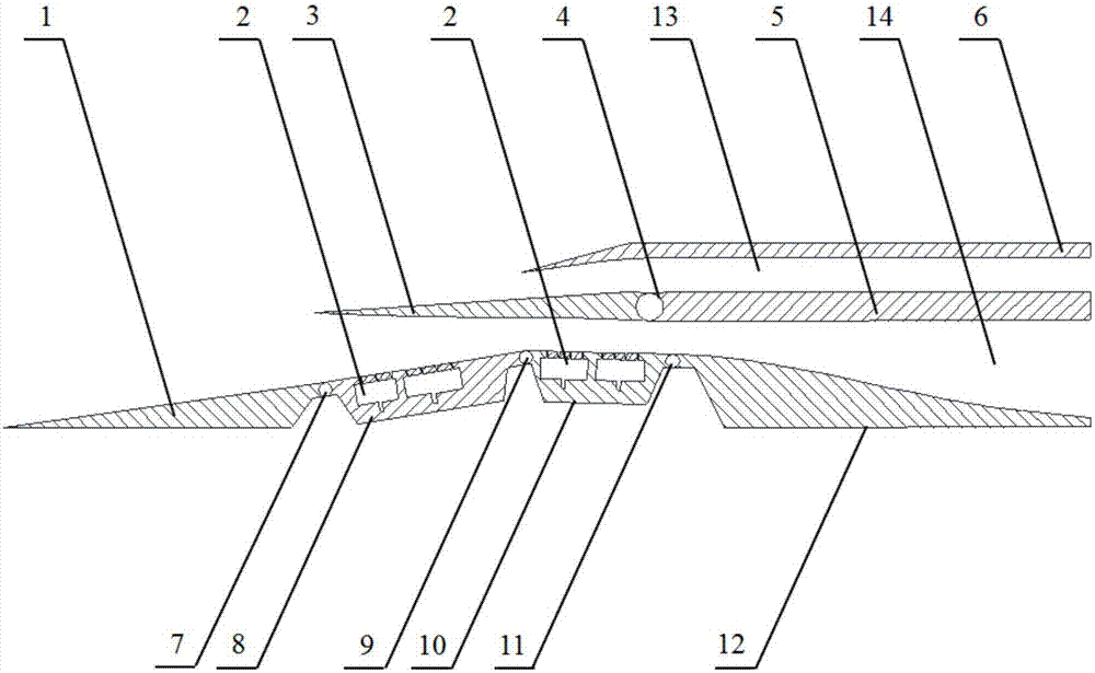
[0022] see figure 1 and figure 2 As shown, the present invention discloses a specific embodiment of a high-performance rectangular dual-channel external parallel TBCC inlet, including a high-speed channel 13 extending from front to rear, a low-speed channel 13 located inside the high-speed channel and extending from front to rear side by side with the high-speed channel Passage 14, primary compression surface 1, passage divider 5 between the high-speed passage and the low-speed passage, rotating lip cover 3 hinged at the front end of the passage divider 5 and extending forward; the outer wall of the high-speed passage 13 is the high-speed passage lip Cover 6, the inner wall surface of the low-velocity channel 14 includes a movable contraction section 8 hinged at the rear end of the primary compression surface 1, a movable throat section 10 hinged at the rear end of the movable contraction section 8 and extending backward, connected to the movable The movable diffuser section 12 at the rear end of the throat section. The primary compression surface 1 is fixed and hinged with the movable contraction section 8 at the first control point 7, the movable contraction section 8 and the movable throat section 10 are hinged at the second control point 9, the movable throat section 10 and the movable expansion The segment 12 is hinged at the third control point 11 . The inside of the movable constriction section and the inside of the movable throat section 10 are provided with a discharge cavity 2, and the purpose of the discharge cavity is to control the shock wave boundary layer interference and improve the performance of the air inlet.
[0023] Please reunite Figure 4 As shown, in order to be able to control the rotation of the rotary lip cover 3, a drive system for driving the rotary lip cover 3 to rotate is also provided in this embodiment. At least one side of the movable contraction section 8 extends outward and is connected to the connecting plate of the rotating lip cover 3; the driver drives the connecting plate to move outward or inward, thereby driving the rotating lip cover to rotate outward or inward.
[0024] Please reunite Figure 5 As shown, in order to be able to control the activities of the movable shrinkage section 8, the movable throat section 10, and the movable diffuser section 12, the present embodiment also includes a first rocker 18 and a second rocker 19, the movable The rear end of the contraction section 8 is hinged with the upper end of the first rocker 18, the rear end of the movable throat section 10 is hinged with the upper end of the second rocker 19, and the lower end of the first rocker 18 is connected with the second rocker 19. The lower ends are all hinged on the horizontal actuating rod 20 extending from the front to the rear. The horizontal actuating rod 20 can be driven forward by a motor or retracted backwards. Since the two ends of the first rocking rod 18 and the two ends of the second rocking rod 19 are hinged, when the horizontal actuating rod 20 moves toward the After retracting, pull the lower ends of the first rocker 18 and the second rocker 19 to move backward so that the upper end of the first rocker 18 and the upper end of the second rocker 19 respectively pull the movable contraction section 8 and the movable throat section 10 Move away from the direction of the rotating lip cover 3, so that the area of the throat is enlarged. On the contrary, when the horizontal actuating rod 20 is stretched out forward, the movable constriction section 8 and the movable throat section 10 move towards the direction close to the rotating lip cover 3, so that the area of the throat is reduced, and details are not repeated here.
[0025] like figure 2 As shown, when the incoming flow Mach number is the mode switching Mach number, the mode switching process starts, and the rotating throat 3 starts to rotate counterclockwise until it contacts the front edge of the movable contraction section 8, and the mode switching Completion, the high-speed passage 13 of the air inlet works, and the low-speed passage 14 is closed. When the Mach number continues to increase, the high-speed passage is no longer adjusted until the incoming Mach number reaches the maximum Mach number in the working range, and the compression wave system of the front body of the inlet port is attached to the lip cover 6 of the high-speed passage.
[0026] The working method of the present invention is: when the working Mach number is less than the mode conversion Mach number, the first control point 7, the second control point 9 and the third control point 11 are adjusted to make the movable contraction section 8, the movable throat Section 10, the position of the movable expansion section 12 changes, resulting in the lower wall height of the low-speed passage 14, the throat area expands, and the shrinkage ratio in the intake duct decreases to ensure its normal start. After the intake duct starts, press a certain Regularly adjust the control point, narrow the throat to the corresponding position under the Mach number, and at the same time adjust the rotating lip cover 3 according to a certain law, so that the flow of the intake port matches the flow of the engine.
[0027] In the high-performance rectangular dual-channel external parallel TBCC inlet provided by the present invention, the secondary compression surface of the high-speed channel and the lip cover of the low-speed channel are combined into one, and serve as a mode switching valve, which simplifies the structure of the intake channel and improves reliability. Increase. And by rotating the lip cover 3, the movable shrinkage section 8, the movable throat section 10, and the movable diffuser section 12, the variable adjustment of the throat of the low-speed passage can be made to greatly improve the starting performance of the air inlet, and widen the Stable operating range for low-speed channels.
[0028] In addition, in order to better design the structure of this embodiment to form a practical finished product based on the specific implementation of the above-mentioned high-performance rectangular dual-channel external parallel TBCC inlet, the present invention also provides a Example of design method.
[0029] The design method includes the following steps:
[0030] (a) Determine the respective design point Mach number and capture flow rate of the dual channels according to the flight Mach number range and design the aerodynamic profile 13 of the high-speed channel;
[0031](b) Determine the position of the rotation hinge point (4) between the lip cover rotation lip cover and the channel partition. The specific position should be: ) reflection point on the lower wall of the expressway. On this basis and construct low-speed channel (14);
[0032] (c) Design the minimum aerodynamic profile of the low-speed channel 14 according to the cruise Mach number and compression requirements;
[0033] (d) Determine the maximum aerodynamic profile of the low-speed channel 14 according to the maximum flow required by the flight;
[0034] (e) determine the control points and design the lower wall surface of the low-velocity channel 14 as a variable structure, select the control points, and carry out the variable structure design;
[0035] (f) Determine the regulation of the movable throat adjustment 10 and the rotating lip cover 3 according to the numerical simulation;
[0036] (g) Carry out aerodynamic experiments to verify the working performance and starting performance of the inlet.
[0037] Further, step (a) includes the following sub-steps:
[0038] (a1) Select the maximum value within the flight Mach number range as the Mach number of the design point of the high-speed passage, and select the captured flow rate according to the maximum flow rate required by the engine; adopt the form of double shock wave external compression for wave distribution, and select the flow rate according to the length of the inlet precursor and total compression requirements, assign the first-level deflection angle and the second-level deflection angle; among them, the shock wave angle β and the airflow deflection angle δ satisfy the relationship:
[0039]
[0040] In the formula, M is the Mach number of the oblique shock wave front, and k is the specific heat ratio;
[0041] (a2) Determine the internal shrinkage ratio of the high-speed flow channel; the internal shrinkage ratio is between 1.1 and 1.3;
[0042] (a3) Determine the throat area of the high-speed passage, define the throat height of the high-speed passage as h0, the length of the inner constriction section is 3 to 4 times the length of the throat, and give the entrance height of the air inlet, and obtain it according to the definition of the inner constriction ratio Throat height of the expressway, calculate the length of the inner contraction section according to the throat height of the expressway;
[0043] (a4) The angle between the outer surface of the lip cover and the horizontal line is 9°~12°.
[0044] Step (b) includes the following sub-steps:
[0045] (b1) Select the Mach number of the design point of the low-speed channel. The selection of the Mach number should first ensure that it is not greater than the mode conversion Mach number and close to the cruise Mach number of the low-speed channel; since the secondary compression surface has been set as a rotating lip cover, a The stage compression surface angle is fixed, so according to the design Mach number of the low-speed channel (14), the shock angle β can be directly determined; where the shock wave angle β and the airflow deflection angle δ satisfy the relational expression:
[0046]
[0047] In the formula, M is the Mach number of the oblique shock wave front, and k is the specific heat ratio;
[0048] With the rotation hinge point 4 as the center of the circle, the length of the secondary compression surface as the radius and the intersection of the primary compression surface is the position of the lip cover at the design point of the low-speed channel; if this is the captured flow rate of the designed low-speed channel, it meets the maximum flow requirements, you need to return to step (a) to redesign;
[0049] (b2) Determine the internal shrinkage ratio of the low-speed runner, define A 1 is the area of the entrance section of the low-velocity channel, A 2 is the area of the throat section of the low-velocity channel; the internal contraction ratio Ar t is the ratio of the area of the entrance section of the low-velocity passage to the throat section; the internal contraction ratio Ar t The determination of is carried out according to the method of starting ability factor S; the definition of starting ability factor S is:
[0050] S=(Ar t -AR t,等熵极限 )/(AR t,Kantrowitz极限 -AR t,等熵极限 );in,
[0051]
[0052]
[0053] In the formula, M0 is the flight Mach number, γ=1.4; the value range of S is 0.75~0.85;
[0054] (b3) Determine the minimum throat area according to the selected design Mach number, the specific method is as follows: Definition: A 1 is the area of the entrance section of the low-velocity channel, A 0 is the area of the throat section of the low-velocity channel; according to the principle of flow conservation, the throat area A 0 for:
[0055]
[0056] where Ma 1 is the inlet Mach number; Ma 0 Ψ is the throat Mach number, Ψ is the discharge coefficient and generally takes 1 when designing, σ is the total pressure recovery coefficient and takes 80% to 95%; q(M) is the flow function, and the specific function form is:
[0057]
[0058] In the formula, M is the Mach number, k=1.4, according to experience, the throat Mach number Ma should be guaranteed 0 In the range of 1.2 to 1.4;
[0059] (b4) Determine the initial maximum area of the throat according to the maximum flow required by the engine at take-off, and the specific method is as follows: According to the flow formula:
[0060]
[0061] Among them, is the maximum flow required by the engine;
[0062]
[0063] k=1.4, R=287.06, is the total pressure at the inlet, σ is the recovery coefficient of the total pressure, which is 80% to 95% during design, The total temperature is considered to be constant during design, Ma t is the throat Mach number, q(M) is the flow rate, A 0 is the minimum throat area; when the throat Mach number Ma is in the range of 0.7-0.8, the maximum throat area can be obtained according to the above flow formula;
[0064] (b5) determine the length of the throat, the specific method is as follows: under the design state of the low-speed passage, define the throat height as H, the length of the throat as L, and the value of L/H is in the range of 2-4;
[0065] (b6) Determine that the expansion angle of the diffuser section is within 3 to 7 degrees;
[0066] (b7) According to the given capture flow rate, internal contraction ratio, maximum and minimum throat area, first-order compression angle, expansion angle, and throat length, and determine based on mutual hinge constraints and geometric relationships, it is guaranteed to be variable The maximum/minimum aerodynamic profile can be determined under the condition that the throat section 10 is kept horizontal at all times.
[0067] The design method of the variable mechanism is as follows: Design the rigid deformation mechanism:
[0068] (1) The movable diffuser section 12 is made of a spring steel plate;
[0069] (2) Based on the minimum throat profile designed in the design step (c), select the hinge point: take the intersection point of the rotating lip cover and the primary compression surface as the first control point 7, and the incident shock wave generated by the rotating lip cover The reflection point on the lower wall is used as the second control point 9, and the intersection of the low-velocity channel diffuser section and the throat is used as the third control point (11);
[0070] (3) In steps (c) and (d), the maximum height hmax of the throat of the low-speed channel 14 and the minimum height hmin of the throat are respectively determined. From the geometric relationship, it can be concluded that the minimum length of the first rocker 18 is hmax- hmin, considering the force of the mechanism and the displacement of the horizontal actuating rod 20, the length l1 of the first rocker 18 is selected as 1.7 times the minimum length; in order to keep the position of the movable throat section 10 horizontal when moving, the first The length l2 of two rocking bars (19) is selected as 1.9 times of minimum length;
[0071] (4) Take the minimum aerodynamic profile as the benchmark, take the first control point 7 and the second control point 9 as the center respectively, and draw a circle with the lengths l1 and l2 of the rocker, and the distance between the two circles and the horizontal baseline determined according to the overall structural requirements of the aircraft The intersection point is defined as the hinge position of the first rocker, the second rocker and the horizontal actuator;
[0072] (5) Judge whether the connecting rod deformation mechanism designed in (1)-(4) can achieve the expected deformation requirements through motion simulation, if not, adjust the parameters and repeat the design steps of (1)-(4).
[0073] In step f, the adjustment law of the flow and the rotating lip cover should be according to the flow formula described in step (b4) Relation to step (b3) area: Adjust and transform the formula to know:
[0074]
[0075] According to the above formula, as long as the Mach number of the incoming flow is known, the area of the throat and the lip cover can be adjusted to ensure the working performance of the inlet.
[0076] Wherein the design method of venting groove 2 is as follows
[0077] Arrange the deflation section of the boundary layer: According to the one-dimensional flow calculation formula and the corresponding geometric relationship, determine the wave system structure at different working Mach numbers, and then determine that the incident point of the shock wave generated by the rotating lip cover 3 is on the movable contraction section 8 Then, according to this range, the deflation slots 2 are set up on the movable contraction section 8 and the entire movable thick section 10, so that the incident shock wave always hits the deflation area of the boundary layer, and works normally in the air inlet At the same time, the positive shock wave at the end can stabilize the movable throat section 10 to ensure the stable operation of the air inlet; the deflation slot 2 uses multi-zone independent deflation control measures; the deflation flow rate should be less than 3% of the total capture flow rate.