
An Online Energy Saving System of Two Independent Hydraulic Stations

An energy-saving system and hydraulic station technology, which is applied in the directions of fluid pressure actuation system components, fluid pressure actuation devices, mechanical equipment, etc. Effect

Active Publication Date: 2019-06-07
江苏联峰实业有限公司
View PDF7 Cites 1 Cited by
  • Summary
  • Abstract
  • Description
  • Claims
  • Application Information

AI Technical Summary

Problems solved by technology

How to merge the hydraulic station has become a problem. The technicians are also trying to connect the two oil inlet pipes and the two oil return pipes, and add valve accessories. However, oil leakage will actually occur, and the liquid level of one oil tank will drop after it is put into use. , the liquid level of the other oil tank has risen, and it cannot be used normally. Therefore, the two hydraulic stations are merged to solve the problem of oil leakage, so that the two production lines of the high-end line share one hydraulic station for energy saving. A new method needs to be proposed to solve the problem.

Method used


Image

  • An Online Energy Saving System of Two Independent Hydraulic Stations
  • An Online Energy Saving System of Two Independent Hydraulic Stations

Examples


Embodiment 1

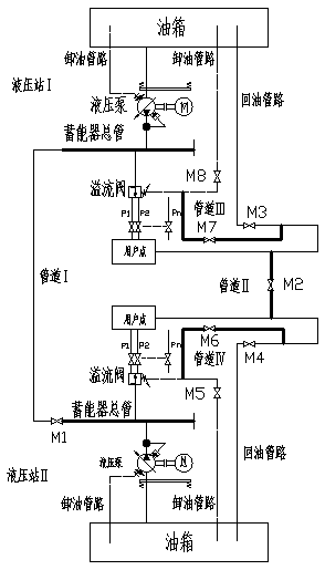
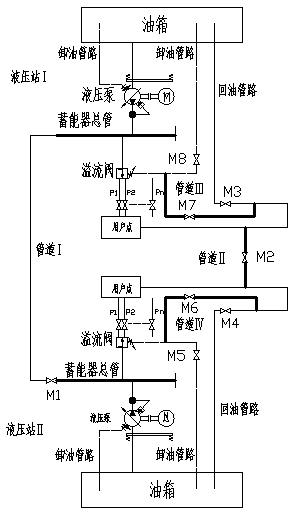
[0017] As shown in the figure, an online energy-saving system of two independent hydraulic stations, including hydraulic station Ⅰ and hydraulic station Ⅱ, there is a pipeline Ⅰ between the accumulator headers of hydraulic station Ⅰ and hydraulic station Ⅱ, and there is a valve on the pipeline Ⅰ M1; the oil return pipelines of hydraulic station Ⅰ and hydraulic station Ⅱ are connected through pipeline Ⅱ, and valve M2 is set on pipeline Ⅱ, valve M3 is set on the oil return pipeline of hydraulic station Ⅰ, and valve M4 is set on the oil return pipeline of hydraulic station Ⅱ ; There is a pipeline III between the oil return pipeline and the oil unloading pipeline of the hydraulic station Ⅰ, and a pipeline IV is installed between the oil return pipeline and the oil unloading pipeline of the hydraulic station II, the valve M7 is set on the pipeline III, and the valve M6 is set on the pipeline IV ; There is a valve M8 on the unloading pipeline of the hydraulic station Ⅰ, and a valve M...

Embodiment 2

[0024] As shown in the figure, an online energy-saving system of two independent hydraulic stations, including hydraulic station Ⅰ and hydraulic station Ⅱ, there is a pipeline Ⅰ between the accumulator headers of hydraulic station Ⅰ and hydraulic station Ⅱ, and there is a valve on the pipeline Ⅰ M1; the oil return pipelines of hydraulic station Ⅰ and hydraulic station Ⅱ are connected through pipeline Ⅱ, and valve M2 is set on pipeline Ⅱ, valve M3 is set on the oil return pipeline of hydraulic station Ⅰ, and valve M4 is set on the oil return pipeline of hydraulic station Ⅱ ; There is a pipeline III between the oil return pipeline and the oil unloading pipeline of the hydraulic station Ⅰ, and a pipeline IV is installed between the oil return pipeline and the oil unloading pipeline of the hydraulic station II, the valve M7 is set on the pipeline III, and the valve M6 is set on the pipeline IV ; There is a valve M8 on the unloading pipeline of the hydraulic station Ⅰ, and a valve M...


PUM


Abstract

The invention provides an online energy-saving system with two independent hydraulic stations. The online energy-saving system comprises a first hydraulic station and a second hydraulic station, wherein a first pipeline is arranged between an energy accumulator header pipe of the first hydraulic station and an energy accumulator header pipe of the second hydraulic station, and a valve M1 is arranged on the first pipeline; an oil return pipeline of the first hydraulic station is connected with an oil return pipeline of the second hydraulic station through a second pipeline, and a valve M2, a valve M3 and a valve M4 are arranged on the second pipeline, the first hydraulic station and the second hydraulic station separately; a third pipeline is arranged between the oil return pipeline and anoil discharge pipeline of the first hydraulic station, a fourth pipeline is arranged between the oil return pipeline and an oil discharge pipeline of the second hydraulic station, and a valve M7 and avalve M6 are arranged on the third pipeline and the fourth pipeline separately; and a valve M8 and a valve M5 are arranged on the oil discharge pipeline of the first hydraulic station and the oil discharge pipeline of the second hydraulic station separately. The online energy-saving system with the two independent hydraulic stations has the beneficial effects that one hydraulic station can be used for two production lines by only switching on or switching off the valves, the design is ingenious, the structure is simple, the oil expelling problem does not exist when power is supplied after combination, and energy saving is achieved finally; and the production efficiency can be guaranteed, and one hydraulic station can be used as a standby machine.

Description

technical field [0001] The invention relates to the technical field of steel rolling equipment, in particular to an online energy-saving system of two independent hydraulic stations. Background technique [0002] With the acceleration of my country's heavy industrialization process, the supply of coal, electricity and oil continues to be tight. The energy consumption of my country's iron and steel industry has accounted for 1 / 6 of the energy consumption of the whole society, and it is a major energy-saving player. Energy conservation and environmental protection are the general trend of the development of Chinese enterprises, and it is urgent to work on energy conservation in the national iron and steel industry. Through the investigation and research on the high-line equipment site, the workshop technicians discussed the possibility of merging the two independent hydraulic stations (hydraulic systems with multi-stage pressure regulation) to save electricity while meeting pr...

Claims


Application Information

Patent Timeline
Patent Type & Authority Patents(China)
IPC IPC(8): F15B21/00
Inventor 张林倪瑞童黄永祥
Owner 江苏联峰实业有限公司
Learn More