Power switch gas leakage detection method and system

A technology of gas leakage detection and gas detection system, which is applied in the direction of using liquid/vacuum degree to measure liquid tightness, measuring the rate of increase and deceleration of fluid, and testing fluid tightness by using light, etc. Time-consuming detection, equipment burnout and other problems, to achieve the effect of shortening the detection time, optimizing the sequence of leak detection, and improving the efficiency of leak detection

Inactive Publication Date: 2018-01-12
YUNNAN POWER GRID CO LTD ELECTRIC POWER RES INST
View PDF6 Cites 2 Cited by
  • Summary
  • Abstract
  • Description
  • Claims
  • Application Information

AI Technical Summary

Problems solved by technology

[0005] This application provides a gas leakage detection method and system for a power switch to solve the blind and disorderly detection of leakage in various parts of the power switch equipment in the prior art. Carrying out maintenance and treatment, causing the equipment to burn down and causing huge economic losses

Method used


Image

  • Power switch gas leakage detection method and system
  • Power switch gas leakage detection method and system
  • Power switch gas leakage detection method and system

Examples


Embodiment 1

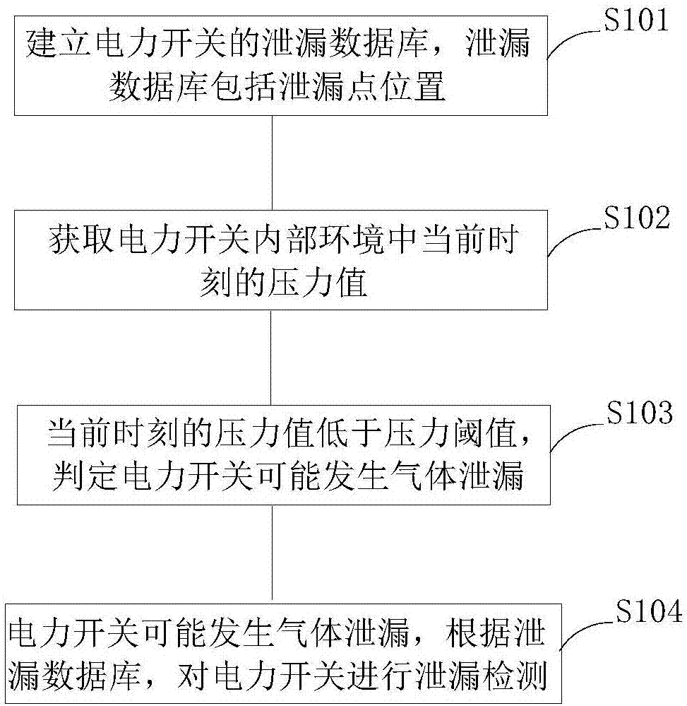
[0046] figure 1 It is a flow chart of a method for detecting gas leakage of a power switch provided in the embodiment of the present application. see figure 1 , the method includes the following steps:

[0047] S101: Establish a leakage database of the power switch, where the leakage database includes historical leakage point locations.

[0048] The leakage database is an information database of historical leakage points. When used for the first time, the information in the leakage database can be established through manual input, and then the leakage database can be established through automatic saving during use.

[0049] S102: Obtain the pressure value at the current moment in the internal environment of the power switch.

[0050] The gas volume inside the power switch is directly related to the pressure value of the power switch. If the power switch gas leaks, the gas pressure inside the power switch will decrease with the reduction of the gas volume. In a possible imp...

Embodiment 2

[0086] Please refer to the attached Figure 5 , which shows a schematic diagram of a power switch gas leakage detection system provided in this embodiment.

[0087] An embodiment of the present application provides a power switch gas leakage detection system, including:

[0088] The database establishment unit 1 is used to establish a leakage database of the power switch, and the database includes historical leakage point locations.

[0089] The pressure value acquisition unit 2 is used to acquire the current moment pressure value in the internal environment of the power switch, and the pressure value acquisition unit 2 includes a pressure sensor.

[0090] The pressure value judging unit 3 is configured to judge that gas leakage may occur in the power switch when the pressure value at the current moment is lower than the pressure threshold.

[0091] The gas leakage detection device 4 is used for performing leakage detection on the power switch according to the leakage databa...


PUM


Abstract

The invention provides a power switch gas leakage detection method and system. The method includes the steps: building a leakage database of a power switch; acquiring a pressure valve of the current moment in the internal environment of the power switch, and judging that the power switch possibly has gas leakage when the pressure valve of the current moment is lower than a pressure threshold value; performing leakage detection on the power switch according to the leakage database when the power switch possibly has gas leakage. The leakage database comprises history leakage point positions. Relative to the prior art, when leakage is detected by the aid of infrared imaging technology, detection is blindly disordered. According to the power switch gas leakage detection method and system, compared with a historical database, leakage detection orders in power switch gas leakage detection are optimized, leakage point detection time is shortened, and leakage detection efficiency is improved.

Description

technical field [0001] The present application relates to the technical field of power detection equipment, in particular to a method and system for detecting gas leakage of a power switch. Background technique [0002] Gas-insulated switchgear has the advantages of small size, light weight, good safety, high reliability, and adaptability to harsh environmental conditions, and is widely used in high-voltage and ultra-high-voltage fields. In actual operation, due to factors such as product manufacturing quality, operation loss and improper installation, gas leakage occurs. With the leakage of gas, the gas pressure in the equipment drops. When it is lower than a certain critical value, insulation breakdown will occur, causing the switchgear to burn out, and even affect the operation of the entire circuit network. Therefore, it is urgent to detect the gas leakage of the insulated switchgear in order to find and solve the leakage problem in time . [0003] At present, the most...

Claims


Application Information

Patent Timeline
Patent Type & Authority Applications(China)
IPC IPC(8): G01M3/26G01M3/38
Inventor 刘荣海杨迎春许宏伟何潇郭新良何运华夏桓桓郑欣虞鸿江
Owner YUNNAN POWER GRID CO LTD ELECTRIC POWER RES INST
Why Eureka
Try Eureka