Processor fixing structure, component and computer equipment

A fixed structure and fixed component technology, applied in the computer field, can solve problems such as inability to maintain heat dissipation, difficulty in providing total pressure load requirements for radiators, difficulty in ensuring contact reliability between CPU and processor sockets, etc.

Active Publication Date: 2018-01-12
XFUSION DIGITAL TECH CO LTD
View PDF14 Cites 11 Cited by
  • Summary
  • Abstract
  • Description
  • Claims
  • Application Information

AI Technical Summary

Problems solved by technology

[0004] However, it is difficult to provide the total pressure load demanded by the increased area of ​​the CPU with the current fixed structure of the processor and the heat sink, resulting in an insufficient combination betwee

Method used


Image

  • Processor fixing structure, component and computer equipment
  • Processor fixing structure, component and computer equipment
  • Processor fixing structure, component and computer equipment

Examples


Embodiment 1

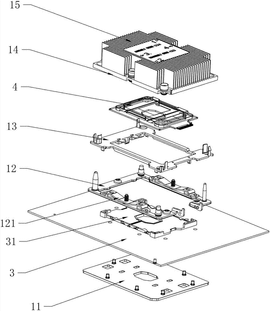
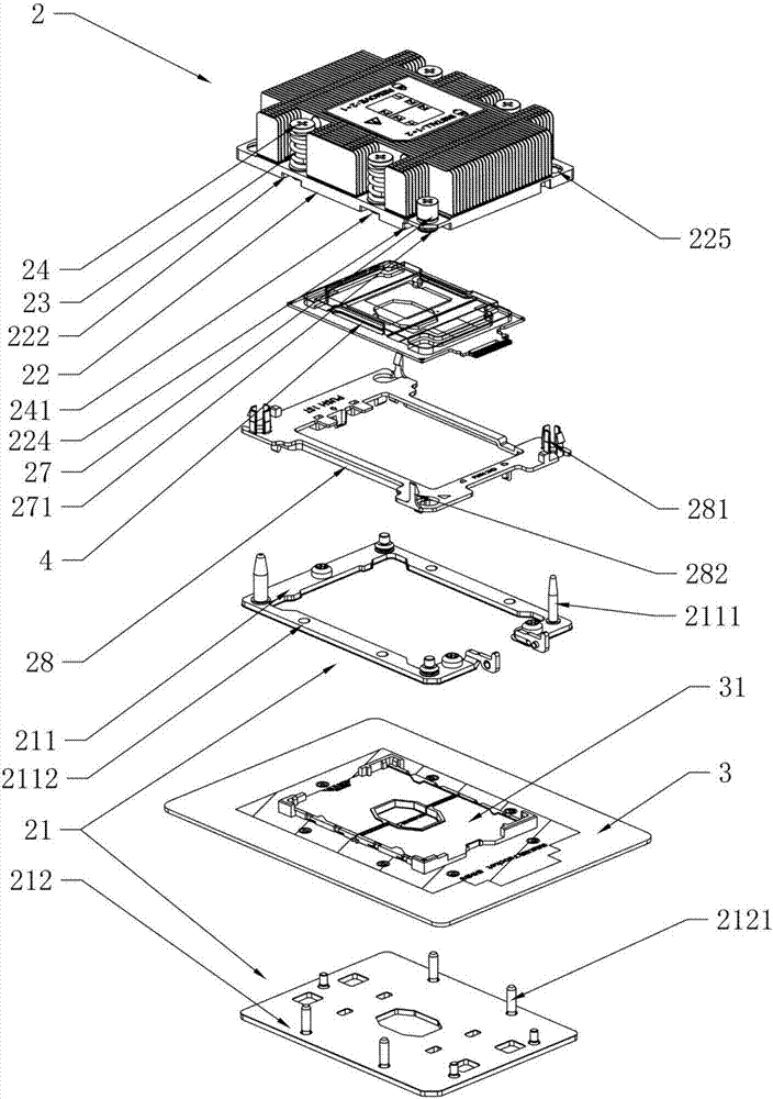
[0052] In order to solve the above problems, this application provides a processor fixed structure, please refer to figure 2 , figure 2 It is an exploded schematic view of the processor fixing structure of the embodiment of the present application, wherein the processor fixing structure 2 includes a heat sink substrate 22 , and the heat sink substrate 22 is in contact with the processor 4 .

[0053] Optionally, the processor fixing structure 2 further includes a fixing component 21. The fixing component 21 is fixed on the processor socket 31 on the PCB 3 , and the radiator substrate 22 in contact with the processor 4 is mounted on the fixing component 21 . Therefore, the heat sink substrate 22 is fixed on the fixing assembly 21 .

[0054] The sides of the heat sink substrate 22 are provided with an elastic structural member and a limiting structural member for limiting the elastic structural member. One end of the limiting structural member passes through the elastic struc...

Embodiment 2

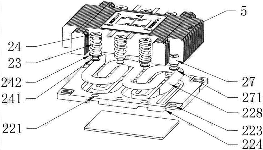
[0058]In this embodiment, on the basis of embodiment 1, as figure 2 with image 3 as shown, image 3 It is a diagram of an embodiment of the processor fixing structure of the embodiment of the present application, wherein the elastic structural member is a compression spring 23, the limiting structural member is a first screw 24, and the compression spring 23 is sleeved on the first screw 24, The diameter of the head end of the first screw 24 is larger than the inner diameter of the compression spring 23 , and the two ends of the compression spring 23 are located between the head end of the first screw 23 and the radiator substrate 22 . In this case, since the head end of the first screw 24 is larger than the inner diameter of the compression spring 23, the compression can be achieved by tightening the first screw 24 to shorten the distance between the head end of the first screw 24 and the radiator substrate 22. The purpose of the spring 23 is to make the elastic force gen...

Embodiment 3

[0080] In this embodiment, on the basis of Embodiment 1, please refer to Figure 8a with Figure 8b , Figure 8a It is an embodiment diagram of the fixed structure of the processor in the embodiment of the present application, Figure 8b It is a diagram of an embodiment of the processor fixing structure of the embodiment of the present application, wherein the limiting structural member is a third screw 25, the elastic structural member is an elastic piece 26, and the curved part located in the middle of the elastic piece 26 is provided with a second Two limiting holes 261, the inner side of the curved portion is opposite to the radiator substrate 22, the third screw 25 passes through the second limiting hole 261 and is connected to the radiator substrate 22, the third screw The outer diameter of the head portion of 25 is larger than the inner diameter of the second limiting hole 261 , and the two ends of the elastic piece 26 are respectively connected with the heat sink sub...


PUM


Abstract

The invention relates to the technical field of computers, and in particular to a processor fixing structure. The processor fixing structure comprises a radiator substrate in contact with a processor,wherein the radiator substrate is fixed on a fixing component at a processor slot on a printed circuit board PCB; an elastic structural member and a spacing structural member for spacing the elasticstructural member are arranged on the side edge of the radiator substrate; one end of the spacing structural member penetrates the elastic structural member to be connected with the fixing component;and the elastic structural member is located between the other end of the spacing structural member and the radiator substrate. According to the processor fixing structure, the elastic structural member is compressed through shortening the distance between the other end of the spacing structural member and the radiator substrate, so that the elastic structural member gives elastic force to the spacing structural member and the radiator substrate at the same time; and the spacing structural member penetrates through the elastic structural member to be connected with the fixing component, so that the elastic force of the elastic structural member is converted into pressure from the radiator substrate to a CPU, and then the pressure to the CPU can be enhanced to satisfy an increased total pressure load.

Description

technical field [0001] The present application relates to the field of computer technology, in particular to a processor fixing structure, components and computer equipment. Background technique [0002] In the era of Internet, big data and cloud computing, higher requirements are put forward for the transmission and processing speed, storage capacity and high-performance computing capacity of massive data. Due to the impact of intensive computing, higher requirements are placed on the processing capacity of the server. [0003] One of the current ways is to increase the area of ​​a single processor, and integrate more or even more complex circuits in the processor after the area is increased to improve the processing capability of a single processor, such as Intel's server central processing unit (Central Processing Unit, referred to as CPU) products, the number of pins has been increased from 2011 to 3647, which has increased the area of ​​a single processor by nearly 80%...

Claims


Application Information

Patent Timeline
IPC IPC(8): G06F1/18G06F1/20
CPCG06F1/183G06F1/20H01L23/427H01L23/3672H01L23/4006H01L2023/4031H01L2023/4062H01L2023/4081H01L2023/405H01L2023/4087
Inventor 毛永海林杉李定方
Owner XFUSION DIGITAL TECH CO LTD
Why Eureka
Try Eureka