
A leakage circuit for a diode reverse leakage current

A bleeder circuit and diode technology, applied in electrical components, output power conversion devices, etc., can solve problems such as power loss and large R1 loss.

Inactive Publication Date: 2018-01-12
亚荣源科技(深圳)有限公司
View PDF8 Cites 0 Cited by
  • Summary
  • Abstract
  • Description
  • Claims
  • Application Information

AI Technical Summary

Problems solved by technology

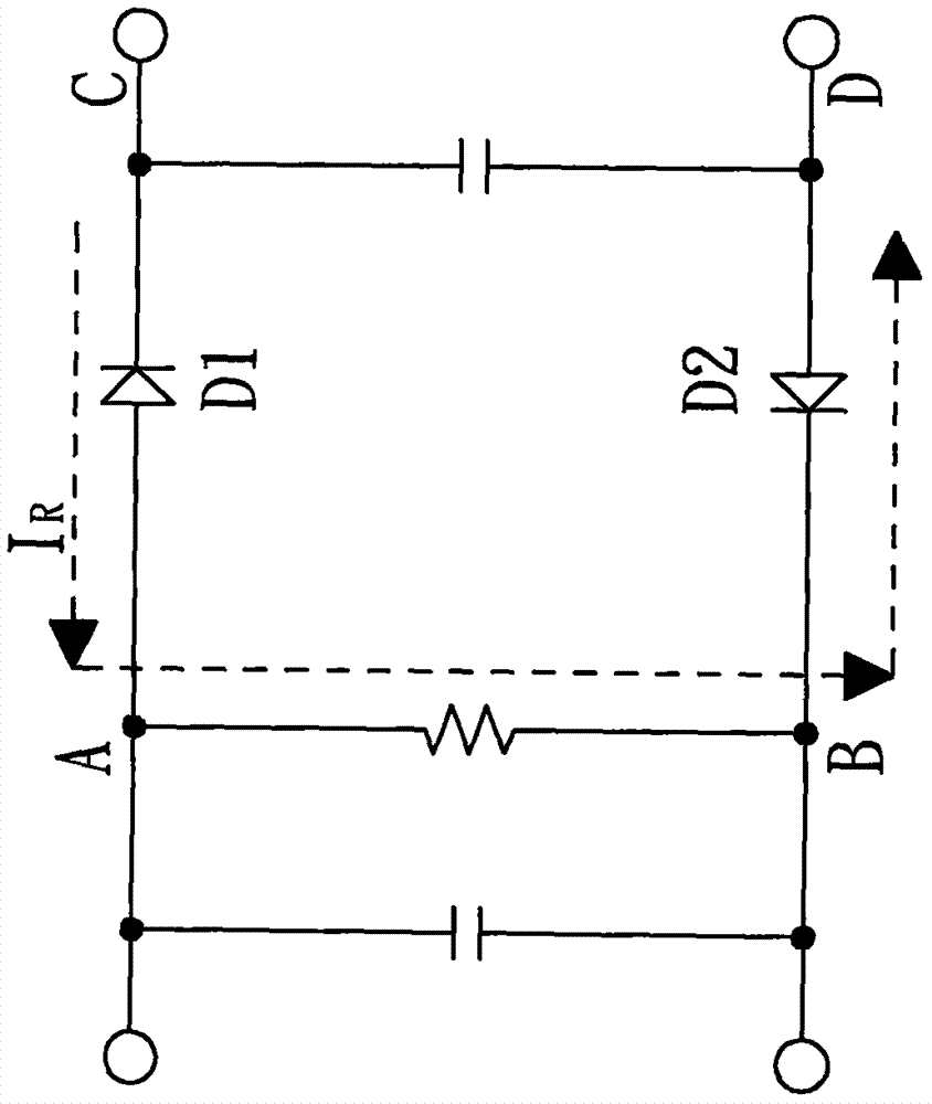
However, when the circuit is operating normally, the AB terminal will cross a high-voltage direct current, and R1 is continuously connected to the AB terminal. According to p=V 2 / R will make R1 lose a lot, up to 1W or more, resulting in unnecessary power loss

Method used


Image

  • A leakage circuit for a diode reverse leakage current
  • A leakage circuit for a diode reverse leakage current
  • A leakage circuit for a diode reverse leakage current

Examples


Embodiment Construction

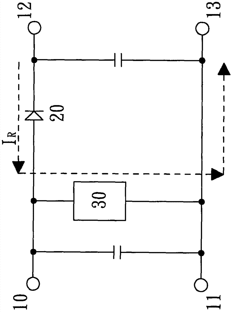
[0019] See image 3 As shown, it is a schematic circuit diagram of the first preferred embodiment of the present invention. The present invention provides a bleeder circuit for diode reverse leakage current, which includes: an input positive terminal (10), an input negative terminal (11), an output positive terminal (12), an output negative terminal (13), a The first diode (20) and a current source device (30). The output positive terminal (12) is coupled with the input positive terminal (10), and the output negative terminal (13) is coupled with the input negative terminal (11). The anode terminal of the first diode (20) is coupled to the input positive terminal (10), and the cathode terminal is coupled to the output positive terminal (12). One end of the current source device is coupled to the anode terminal of the first diode (20), and the other end is coupled between the input negative terminal and the output negative terminal. Wherein, the current source device (30) can ...


PUM


Abstract

The invention brings forward a leakage circuit for a diode reverse leakage current. The circuit comprises an input positive terminal, an input negative terminal, an output positive terminal, an outputnegative terminal, a first diode and a current source device. The output positive terminal is coupled to the input positive terminal, and the output negative terminal is coupled to the input negativeterminal. An anode terminal of the first diode is coupled to the positive input terminal, and a cathode terminal of the first diode is coupled to the output positive terminal. The current source device has one terminal coupled to the anode terminal of the first diode and the other terminal coupled between the input negative terminal and the output negative terminal. When an input voltage is disconnected, since the current value of the current source device is slightly larger than the diode reverse leakage current IR, the voltages at the two terminals of the current source device can be pulledlow enough to reach 1V or less. When the input voltage is normally operating at a high voltage, the current source device still operates, but due to that P = VI, the loss is proportional to the inputvoltage, thereby achieving the purpose of low loss.

Description

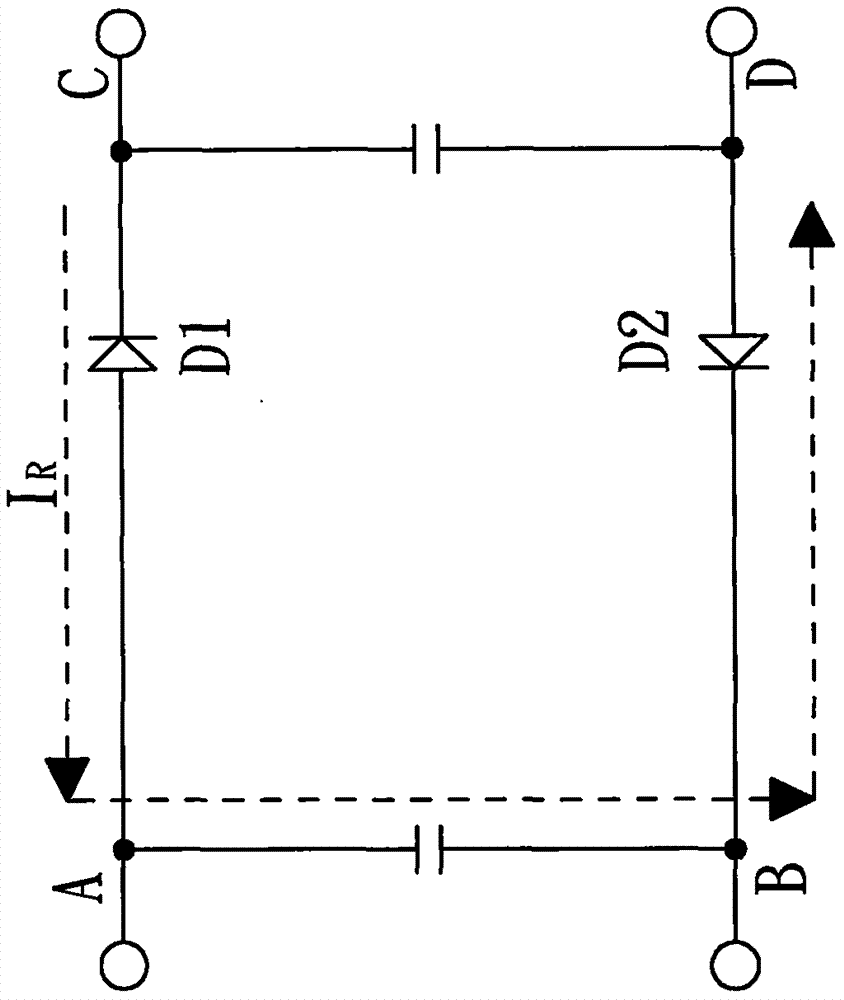
Technical field [0001] The invention relates to a bleeder circuit for diode reverse leakage current, and more particularly to a circuit capable of reducing losses. Background technique [0002] In the design of DC / DC converters, the input terminal will meet the specification requirements of "reverse connection protection". At this time, an active switch such as BJT, MOSFET or even relay will be used to protect the input from disconnection. In order to achieve this The added cost of the protection function is quite high. Therefore, under the premise of a more economical design, it is usually achieved by using Schottky diodes. Schottky diodes have the advantages of low forward bias voltage, simple use and rapid response, and are widely used for input reverse bias protection. The connection method is as figure 1 As shown, figure 1 Using two diodes D1 and D2 when the input voltage is reversed to points A and B, the output terminals C and D can be completely disconnected and isolated ...

Claims


Application Information

Patent Timeline
IPC IPC(8): H02M1/32
Inventor 洪宗良姚宇桐朱炳勋
Owner 亚荣源科技(深圳)有限公司
Learn More