Constant voltage output control system of synchronous rectification primary side feedback flyback power source

A synchronous rectification, primary-side feedback technology, applied in control/regulation systems, conversion of DC power input to DC power output, conversion of AC power input to DC power output, etc., can solve the problem of small on-resistance, obstruction, closed-loop stability problems such as poor constant pressure accuracy

Active Publication Date: 2018-01-12
SOUTHEAST UNIV
View PDF3 Cites 39 Cited by
  • Summary
  • Abstract
  • Description
  • Claims
  • Application Information

AI Technical Summary

Problems solved by technology

[0004] At present, the problem that hinders the application of digital control synchronous rectification primary side feedback flyback converter under high power is: in the case of synchronous rectification, the mature digital approximation two-line inflection point sampling scheme is not accurate
However, under the synchronous rectification structure, the sampling waveform is not suitable for the two-wire sampling scheme: due to the synchronous rectification structure, the on-resistance of the synchronous rectifier tube is small, only a dozen to tens of milliohms, so whether it is continuous current mode ( In CCM) and discontinuous current mode (DCM), there is a problem that the slope of the sampling waveform is small and steep after the inflection point. In addition, in actual situations, synchronous rectification is generally turned off before the inflection point, and at this time it becomes a parasitic diode DSR conduction, forward conduction voltage drop V f is 1V, if it is a knee point sampling, the sampled voltage is V o +V f , at this time, the sampling accuracy will be affected by the position of the inflection point and will deteriorate, resulting in low sampling accuracy and poor follow-up to the inflection point, resulting in poor closed-loop stability and constant voltage accuracy. Therefore, it is necessary to propose a corresponding improved sampling solution for the problem.

Method used


Image

  • Constant voltage output control system of synchronous rectification primary side feedback flyback power source
  • Constant voltage output control system of synchronous rectification primary side feedback flyback power source
  • Constant voltage output control system of synchronous rectification primary side feedback flyback power source

Examples


Embodiment Construction

[0028] In order to illustrate the present invention more clearly, the technical solutions of the present invention will be clearly and completely described below in conjunction with the accompanying drawings and embodiments.

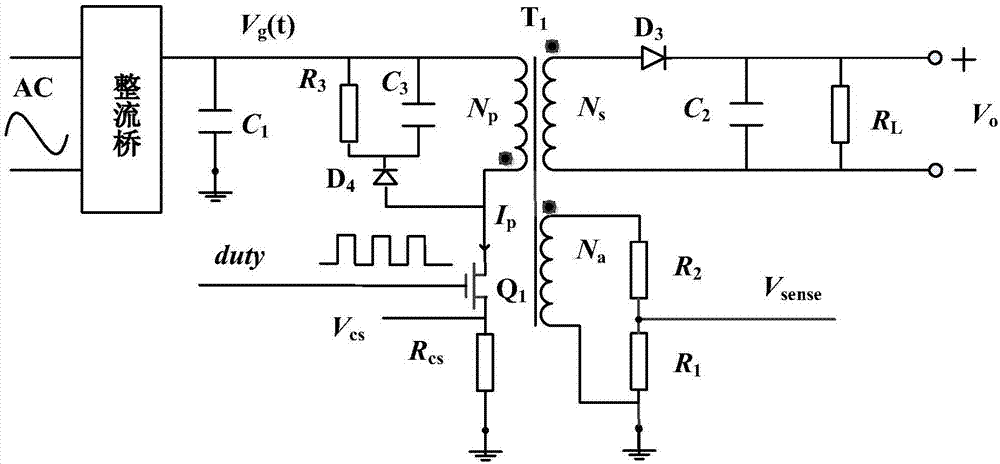
[0029] figure 1 It is a circuit diagram of a primary-side feedback flyback switching converter adopting a diode rectification method in the prior art. The figure shows the main topology of the PSR flyback converter. It mainly includes input rectification and filtering part, transformer part, output rectification and filtering part and sampling part. The alternating current passes through the rectifier bridge to the input filter capacitor C 1 , to get the low-frequency fluctuating DC voltage V g (t), and connected to the transformer T 1 side of the primary winding. The RCD clamping circuit consists of a resistor R 3 , capacitance C 3 and the diode D 4 composed to suppress the switch Q 1 Current overshoot at the moment of turn-off. T 1 There are...


PUM


Abstract

Provided is a constant voltage output control system of a synchronous rectification primary side feedback flyback power source. The control system comprises a single output DAC midpoint sampling module, a sampling error compensation module, a current detection module, a digital control module and a PWM driver module. The single output DAC midpoint sampling module samples a voltage signal Vsense ofan auxiliary winding. The voltage signal Vsense (tmid) at the secondary side current rectification time Tr midpoint moment is output. Midpoint sampling errors are calculated by a compensation algorithm based on the current detection module to correct the sampling voltage on the auxiliary winding at a midpoint. The digital control module utilizes a proportion and an integral to calculate a controlquantity to output the control quantity to the PWM driver module to control a primary side switch tube and a secondary side synchronous rectification tube separately through the compensated midpointvoltage signal and errors e (n) of a fixed value VREF preset by the system, and therefore constant voltage output control on the synchronous rectification primary side feedback flyback power source isachieved.

Description

technical field [0001] The invention belongs to the technical field of isolated switching power supply converters, in particular to a constant voltage output control system of synchronous rectification primary side feedback flyback power supply. Background technique [0002] With the rapid development of the global electronic market, the demand for power management chips will increase in the future. With consumers' increasing demand for thin and light products, the miniaturization of products is a major trend. In addition, with the release of the new generation of Quick Charge 3.0 fast charging technology by Qualcomm, which further increases the charging power of mobile electronic devices to a medium power level of 30 watts, the demand for power will increase in terms of the technical development trend of power supplies. Various topologies of commonly used switching power supplies are classified into categories. Buck and boost are suitable for low-voltage and high-current a...

Claims


Application Information

Patent Timeline
Patent Type & Authority Applications(China)
IPC IPC(8): H02M7/217H02M3/335
CPCY02B70/10
Inventor 徐申周健洋沈为冬陈畅孙伟锋陆生礼时龙兴
Owner SOUTHEAST UNIV
Why Eureka
Try Eureka