Oil-water separating device for biological waste recycling

A technology for oil-water separation device and biological waste, applied in filtration separation, separation method, liquid separation, etc., can solve the problems of reducing the area of ​​oil-water separation device, narrow use range, blockage of water outlet pipe or oil outlet pipe, etc., to speed up oil-water stratification , Improve efficiency and prevent clogging

Inactive Publication Date: 2018-01-16
湖州壤之沃生物技术有限公司
View PDF7 Cites 15 Cited by
  • Summary
  • Abstract
  • Description
  • Claims
  • Application Information

AI Technical Summary

Problems solved by technology

[0003] The patent No. 201310270470.5 of the oil-water separation device invention patent discloses an oil-water separation device, which includes a tank, a liquid inlet fixed to the tank, a liquid outlet, and an oil-water separation core inside the tank. The cover body is fixed, and the cover body includes a sloping plate, and a first oil port is provided at the high end of the sloping plate, which can gradually reduce the area of ​​the horizontal cross-section of the oil-water separation device from the inside of the tank to the first oil port, and the oil-water separation After the core is initially separated, the area of ​​the oil layer floating on the liquid surface gradually decreases, thereby increasing the thickness of the oil slick layer, and then increasing the oil concentration of the first oil port, but its application range in actual use is relatively narrow, and it does not have the ability to filter impurities mechanism, if the oil-water mixture containing more impurities is separated, it will easily lead to blockage of the water outlet pipe or the oil outlet pipe, and the oil-water mixture recovered from biological waste has more impurities, the above-mentioned oil-water separation device is not suitable, so we urgently need a A kind of oil-water separation device suitable for biological waste recycling

Method used


Image

  • Oil-water separating device for biological waste recycling
  • Oil-water separating device for biological waste recycling
  • Oil-water separating device for biological waste recycling

Examples


Embodiment Construction

[0024] The following will clearly and completely describe the technical solutions in the embodiments of the present invention with reference to the accompanying drawings in the embodiments of the present invention. Obviously, the described embodiments are only some, not all, embodiments of the present invention.

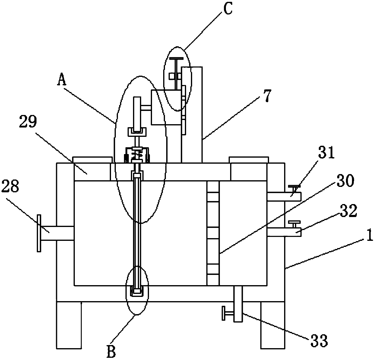
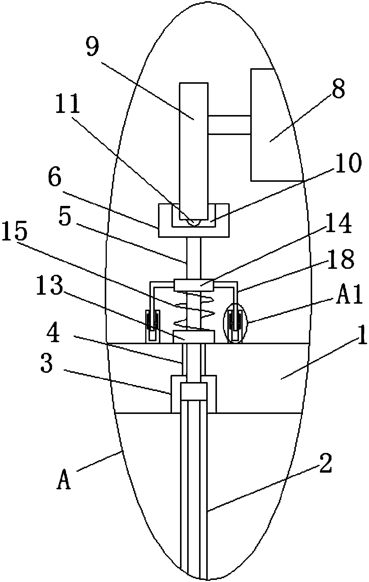
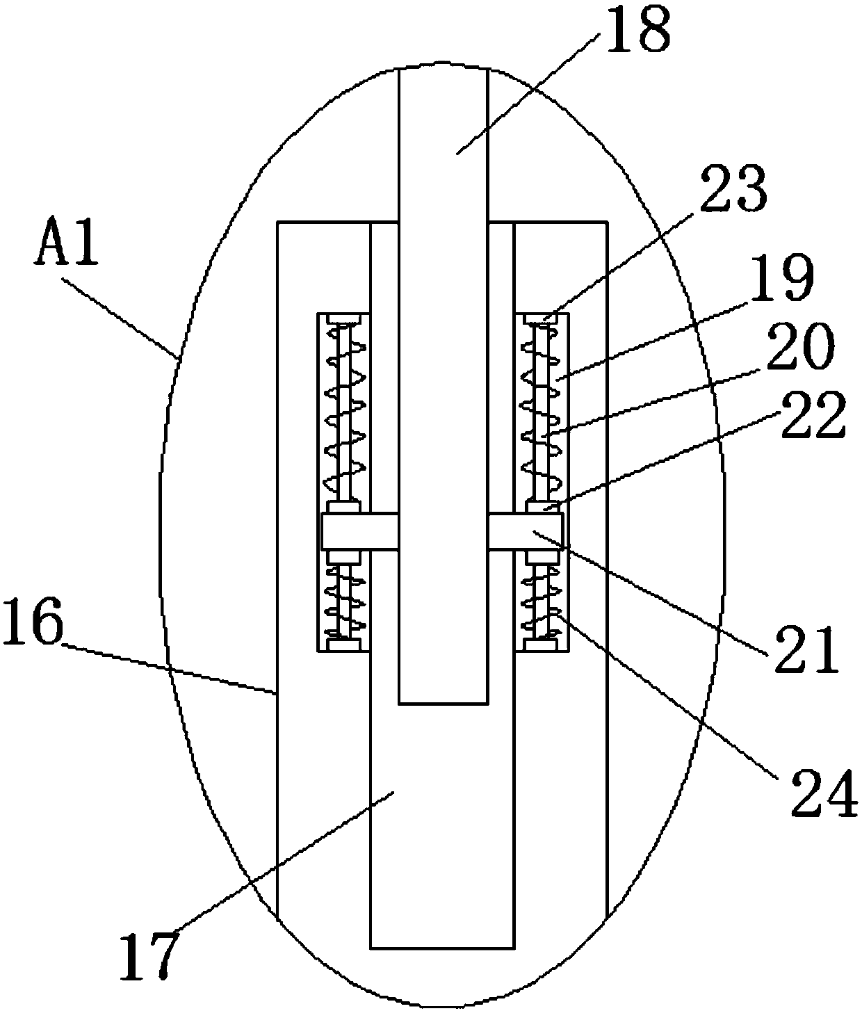
[0025] refer to Figure 1-5 , an oil-water separation device for biological waste recovery, comprising a box body 1, a filter plate 2 is arranged in the box body 1, a transmission module that drives the vibration of the filter plate 2 is arranged on the box body 1, and the transmission module includes a 1. The first card slot 3 on the inner wall of the top. The top side of the filter plate 2 is slidably installed in the first card slot 3. A through hole 4 is opened on the inner wall of the first card slot 3 away from the opening, and the through hole 4 slides A push rod 5 is installed, and both ends of the push rod 5 extend outside the through hole 4, and one end of ...


PUM


Abstract

The invention discloses an oil-water separating device for biological waste recycling. The oil-water separating device comprises a box body, wherein a filtering plate is arranged in the box body; a transmission module for driving the filtering plate to vibrate is arranged on the box body; the transmission module comprises a first clamp slot formed in the inner wall of the top of the box body; thetop side of the filtering plate is glidingly mounted in the first clamp slot; a through hole is formed in the inner wall of one side of the first clamp slot, away from the opening; a mandril is glidingly mounted in the through hole; the two ends of the mandril both extend out of the through hole; one end of the mandril in the first clamp slot is fixed at the top of the filtering plate; a strip fixing block positioned above the box body is fixed at one end of the mandril, away from the filtering plate. According to the oil-water separating device disclosed by the invention, through the filtering plate, impurities can be prevented from blocking an oil outlet pipe or a water outlet pipe, so as to ensure that an oil-water mixture can be normally separated; meanwhile, with vibration of the filtering plate in the box body, the filtering plate can be protected from blockage, and the oil-water layering can be accelerated so as to improve the oil-water separation efficiency.

Description

technical field [0001] The invention relates to the technical field of biological waste treatment, in particular to an oil-water separation device for biological waste recovery. Background technique [0002] Biological waste usually refers to kitchen waste such as leftovers, eggshells, peels, and leaves of vegetables, or things directly dropped by animals and plants such as leaves and branches. Since biological waste contains a lot of oil, if the oil-water mixture Direct discharge will seriously pollute the environment. Therefore, in order to prevent the oil-water mixture from entering the nature when treating biological waste, it is generally necessary to treat the oil-water mixture produced by the treatment of biological waste. At present, people often use oil-water separation devices to separate the oil-water mixture. . [0003] The patent No. 201310270470.5 of the oil-water separation device invention patent discloses an oil-water separation device, which includes a tan...

Claims


Application Information

Patent Timeline
Patent Type & Authority Applications(China)
IPC IPC(8): B01D33/03B01D33/54B01D17/025
Inventor 文洋
Owner 湖州壤之沃生物技术有限公司
Why Eureka
Try Eureka