Sand washing device for geological logging

A technology for geological logging and sand washing, applied in solid separation, wet separation, chemical instruments and methods, etc., can solve problems such as inability to accurately reflect the stratification of cuttings, unsatisfactory sand washing effect, etc., and achieve good sand washing effect. , Improve the efficiency of sand washing and reduce the effect of offset

Inactive Publication Date: 2018-01-16
成都捷科菲友信息技术有限公司
View PDF0 Cites 2 Cited by
  • Summary
  • Abstract
  • Description
  • Claims
  • Application Information

AI Technical Summary

Problems solved by technology

[0004] The purpose of the present invention is: in order to solve the problem that the sand washing effect of the existing mud logging sand washing device is not ideal and cannot accurately reflect the stratification of cuttings, the present invention provides a sand washing device for geological mud logging. Drive the sand washing box to rotate in the sand washing tank filled with clean water, so that the cuttings and mud mixture in the sand washing box are separated to achieve the purpose of sand washing, and the sand washing effect is ideal

Method used


Image

  • Sand washing device for geological logging
  • Sand washing device for geological logging
  • Sand washing device for geological logging

Examples


Embodiment 1

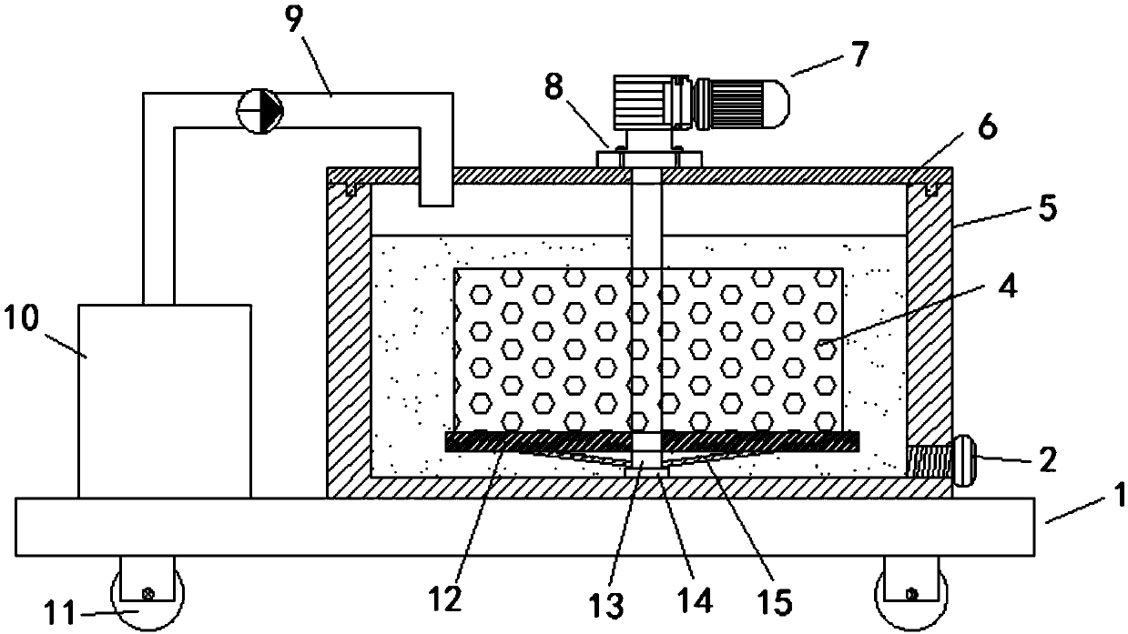
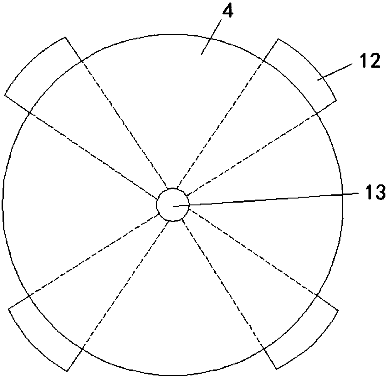
[0024] Such as figure 1 and figure 2 As shown, the present embodiment provides a sand washing device for geological mud logging, including a mounting base 1, a sand washing tank 5 arranged on the mounting base 1, and a sand washing box 4 located in the sand washing tank 5. The sand washing tank 5 is fixed with a cover plate 6, the upper opening of the sand washing tank 5 is provided with a groove, the cover plate 6 is provided with a protrusion matching the groove, and the cover plate 6 is detachably connected by bolts. There is a fixed seat 8, and the fixed seat 8 is provided with a drive assembly 7, and the drive assembly 7 includes a motor and a reducer connected to the output shaft of the motor, the output end of the reducer is fixedly connected to one end of the transmission rod 13, and the The other end passes through the fixed seat 8 and the cover plate 6 and is connected with the bearing seat 14 arranged at the bottom of the sand washing tank 5. The part of the trans...

Embodiment 2

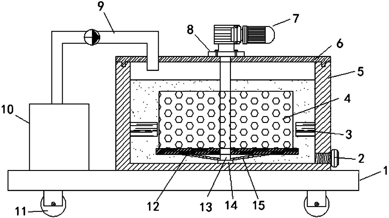
[0026] Such as image 3 As shown, this embodiment is further optimized on the basis of Embodiment 1, specifically: the inner walls of the opposite sides of the sand washing tank 5 are respectively fixed with elastic components 3, when the sand washing tank 4 is rotating due to When a large degree of horizontal deviation occurs due to uneven load bearing, the symmetrically arranged elastic components 3 can reduce the deviation and avoid the sand washing box 4 being rotated due to the uneven distribution of cuttings and mud mixture in the sand washing box 4. When the deviation is large, the connection between the transmission rod 13 and the output end of the reducer is caused to come off, causing sand washing to be interrupted, which affects the smooth development of the work.


PUM


Abstract

The invention discloses a sand washing device for geological logging and relates to the technical field of oil field logging equipment. The device comprises a mounting base, a sand washing pool whichis arranged on the mounting base and a sand washing tank which is located in the sand washing pool, a cover plate is fixedly arranged on the sand washing pool, and a fixing base is detachably connected onto the cover plate; a driving component is arranged on the fixing base, a transmission rod is connected to the driving component, and one end of the transmission rod is fixedly connected with theoutput end of the driving component; the other end of the transmission rod penetrates through the fixing base and is rotatably connected with the cover plate and the bottom of the sand washing pool, the transmission rod penetrates through the sand washing tank and is fixedly connected with the top and the bottom of the sand washing tank respectively, and a bearing plate is fixedly arranged on thetransmission rod; the bearing plate is fixedly connected with the bottom of the sand washing tank, and strengthening connection plates which are used for strengthening and supporting the bearing plateare fixedly connected with the tail end of the transmission rod. According to the sand washing device, the driving component drives the sand washing tank to rotate in the sand washing pool which contains clear water, so that rock debris in the sand washing tank is separated from slurry mixtures, the aim of sand washing is achieved, and the effect of sand washing is ideal.

Description

technical field [0001] The invention relates to the technical field of oilfield mud logging equipment, in particular to a sand washing device for geological mud logging. Background technique [0002] With the continuous development of the social economy and the continuous improvement of industrial production levels, the demand for oil in all walks of life is increasing. However, when obtaining oil, it is necessary to carry out drilling operations on the oil field. The high-speed flowing mud carries the drilling cuttings downhole to the surface, and then the cuttings are filtered out through the shale shaker. For a long time, rock cuttings have been collected manually at the construction site, and then the cuttings stained with drilling mud are washed with water, taken back to the geological room for drying, and then geological analysis. In order to ensure the accuracy of sampling, each geological logging team A certain number of workers must be specially assigned to carry o...

Claims


Application Information

Patent Timeline
Patent Type & Authority Applications(China)
IPC IPC(8): B03B5/62
Inventor 程飞
Owner 成都捷科菲友信息技术有限公司
Why Eureka
Try Eureka