
Silk thread clamping structure arranged on multi-thread embroidery machine

A clamping structure and technology for embroidery machines, which are applied to the mechanism of embroidery machines, embroidery machines, textiles and papermaking, etc., can solve the problems of inaccurate silk thread guidance, expensive equipment, and raised equipment costs, and improve quality and increase Movement effects, effects of reducing the composition of the structure

Pending Publication Date: 2018-01-16
贵州艺雅枝苗绣服饰开发有限公司
View PDF0 Cites 3 Cited by
  • Summary
  • Abstract
  • Description
  • Claims
  • Application Information

AI Technical Summary

Problems solved by technology

[0003] In the prior art, electronic control and precision mechanical components are used to realize plane embroidery, and its structure is complicated, and the equipment cost is expensive. Existing multi-thread embroidery machines have appeared, but their thread guidance is not accurate, and slack is prone to occur, and Most of the existing thread clamping devices are fixed on the embroidery machine. The integrated structure not only increases the cost of the equipment, but also has low flexibility.

Method used


Image

  • Silk thread clamping structure arranged on multi-thread embroidery machine
  • Silk thread clamping structure arranged on multi-thread embroidery machine
  • Silk thread clamping structure arranged on multi-thread embroidery machine

Examples


Embodiment Construction

[0017] The following will clearly and completely describe the technical solutions in the embodiments of the present invention with reference to the accompanying drawings in the embodiments of the present invention. Obviously, the described embodiments are only some, not all, embodiments of the present invention.

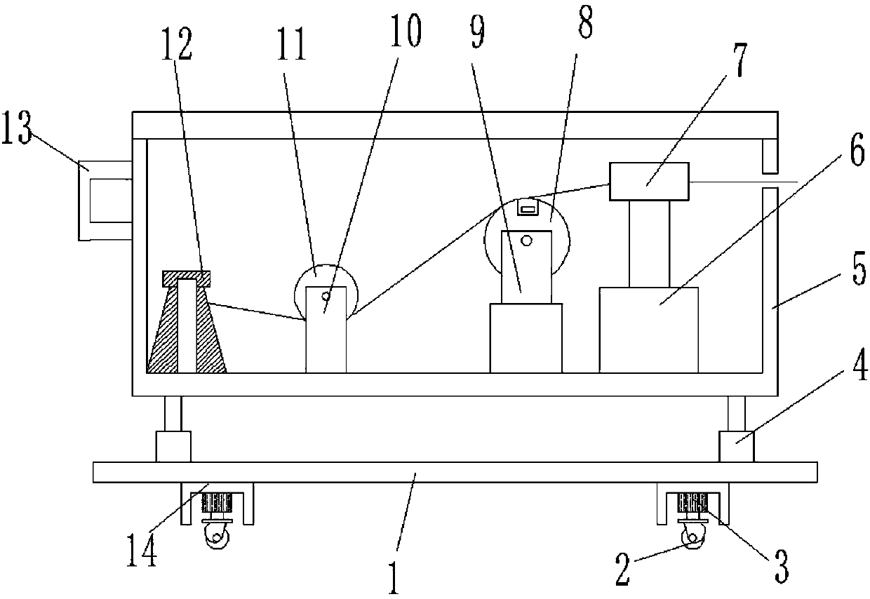
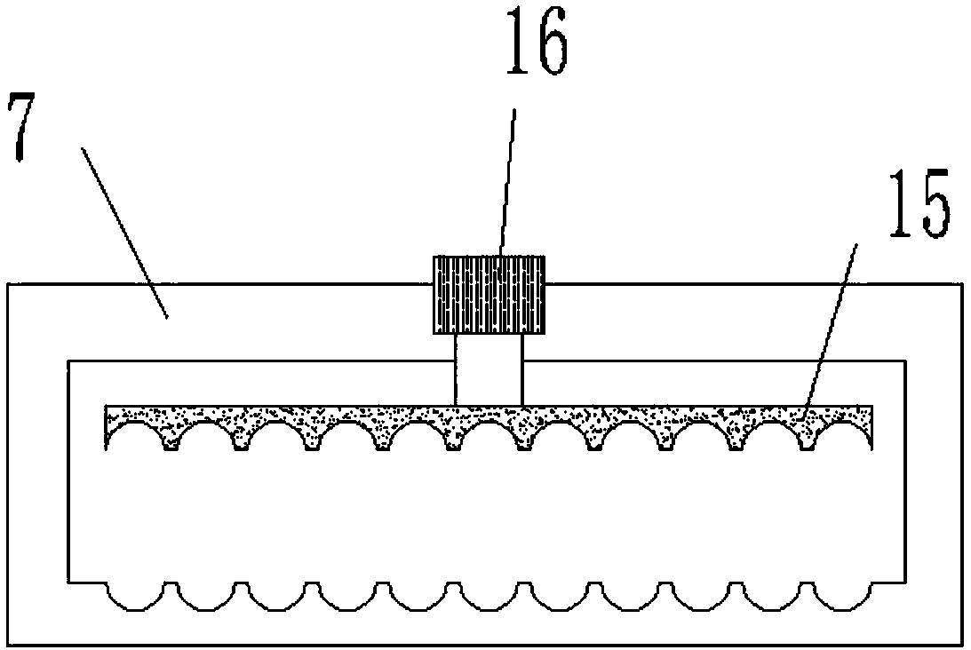
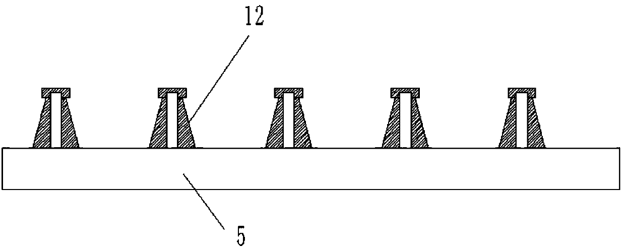
[0018] refer to Figure 1-3 , a thread clamping structure on a multi-thread embroidery machine, including a base 1, the four corners of the top outer wall of the base 1 are fixed with hydraulic cylinders 4 by bolts, and the same dustproof box 5 is fixed on the top outer walls of the four hydraulic cylinders 4 by screws The four corners of the outer wall at the bottom of the base 1 are welded with mounting seats 14, and the outer wall of the bottom of the mounting seat 14 has a mounting groove, the inner wall of the mounting groove is fixed with a first push rod motor 3 by screws, and the dustproof box 5 is welded on one side of the bottom inner wall. A fixed rod, and...


PUM


Abstract

The invention discloses a silk thread clamping structure arranged on a multi-thread embroidery machine. The silk thread clamping structure comprises a base, wherein hydraulic cylinders are fixed at four corners of the top outer wall of the base through bolts; a dustproof box is fixed on the top outer walls of the four hydraulic cylinders through bolts; mounting seats are welded at four corners ofthe outer wall of the bottom end of the base; mounting grooves are formed in the bottom outer walls of the mounting seats; first push rod motors are fixed on the inner walls of the mounting grooves through screws; a fixing rod is welded on one side of the bottom inner wall of the dust-proof box; a bobbin is connected to the outer wall of the fixing rod in a sleeving manner; a first cylinder is fixed on the outer wall of one side, away from the bobbin, of the dust-proof box through bolts. According to the silk thread clamping structure arranged on the multi-thread embroidery machine, the phenomenon that silk threads deviate from the track is eliminated, so that the silk threads keep certain tension degree, and embroidery quality is improved; by means of matching of universal wheels and thebase, the moving effect of equipment is improved, applicable range of the equipment is extended, cost is reduced, and stability of equipment is not reduced.

Description

technical field [0001] The invention relates to the technical field of embroidery machines, in particular to a thread clamping structure on a multi-thread embroidery machine. Background technique [0002] Embroidery is the general term for various decorative patterns embroidered on fabrics with needles and threads. Embroidery is divided into two types: silk embroidery and feather embroidery. It is a kind of art that uses needles and threads to add human design and production to any existing fabric. Embroidery is one of the traditional Chinese folk handicrafts. It has a history of at least two or three thousand years in China. Chinese embroidery mainly includes Su embroidery, Hunan embroidery, Shu embroidery and Yue embroidery. Embroidery techniques include: wrong needle embroidery, random needle embroidery, net embroidery, floor embroidery, lock thread, Nasi, Najin, flat gold, shadow gold, pan gold, velvet paving, velvet scraping, poking yarn, sprinkling thread, Cross-stit...

Claims


Application Information

Patent Timeline
IPC IPC(8): D05C11/08D05C13/00
Inventor 张婕
Owner 贵州艺雅枝苗绣服饰开发有限公司
Learn More