Polygonal machining material positioning guiding device

A technology of positioning, guiding and processing materials, which is applied in positioning devices, metal processing, metal processing equipment, etc., can solve problems such as damage to fixtures, reduce processing efficiency, etc., and achieve the effect of guiding improvement

Pending Publication Date: 2020-05-05
龙口市亨嘉智能装备有限公司
View PDF0 Cites 0 Cited by
  • Summary
  • Abstract
  • Description
  • Claims
  • Application Information

AI Technical Summary

Problems solved by technology

A lathe is a machine tool that mainly uses a turning tool to turn a rotating workpiece. The existing clamping tools of the machine tool are all multi-angle fixtures selected according to the shape of the workpiece. In the prior art, it is difficult to ensure the integrity of the workpie

Method used


Image

  • Polygonal machining material positioning guiding device
  • Polygonal machining material positioning guiding device
  • Polygonal machining material positioning guiding device

Examples


Embodiment 1

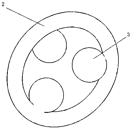
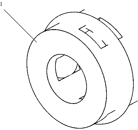
[0029] Such as Figure 1-3 As shown, a positioning and guiding device for polygonal processing materials, the positioning and guiding device is connected to the material pipe 1, and the positioning and guiding device includes an elastic body 2 and a guiding and locking mechanism 3;

[0030] The elastic body 2 is arranged in the groove provided on the material tube 1, and at least three guide locking mechanisms 3 are arranged on the inner side of the elastic body 2;

[0031] The guide locking mechanism 3 is fixedly connected to the inner side of the elastic body 2 at an angle, and the groove of the material tube 1 is provided with the same number of through holes 4 as the guide locking mechanism 3, and the guide locking mechanism 3 is installed In the through hole 4 , part of the guide locking mechanism 3 protrudes from the bottom surface of the through hole 4 .

[0032] The angle between the guide locking mechanisms 3 is 0-120°.

[0033] The depth of the through hole 4 is sm...

Embodiment 2

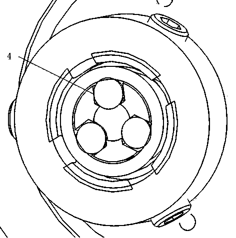
[0036] Such as Figure 4 As shown, a hexagonal prism processing material positioning and guiding device, the positioning and guiding device is connected with the material tube 1, and the positioning and guiding device includes an elastic body 2 and a guiding and locking mechanism 3;

[0037] The elastic body 2 is arranged in the groove provided on the material tube 1, and three guiding locking mechanisms 3 are arranged inside the elastic body 2, and the locking mechanisms can be spherical balls.

[0038] The three guiding and locking mechanisms are distributed at an angle of 120° and fixedly connected to the inner side of the elastic body 2, and the groove of the material tube 1 is provided with three through holes 4, and the guiding and locking mechanisms 3 are installed in the through holes 4, the guide locking mechanism 3 partially protrudes from the bottom surface of the through hole 4, the bottom surface of the through hole 4 is a hemispherical surface, the diameter of th...

Embodiment 3

[0041] An octagonal prism processing material positioning and guiding device, the positioning and guiding device is connected to the material pipe 1, and the positioning and guiding device includes an elastic body 2 and a guiding and locking mechanism 3;

[0042] The elastic body 2 is arranged in the groove provided on the material tube 1, and four guiding locking mechanisms 3 are arranged on the inside of the elastic body 2, and the locking mechanism can be any curved object including a spherical and semi-circular ball;

[0043] The four guiding and locking mechanisms are distributed at an angle of 90° and fixedly connected to the inner side of the elastic body 2. Four through holes 4 are arranged on the groove of the material tube 1, and the guiding and locking mechanisms 3 are installed on the through holes. In the hole 4, the guide locking mechanism 3 partially protrudes from the bottom surface of the through hole 4, the bottom surface of the through hole 4 is a hemispheric...


PUM


Abstract

The invention discloses a polygonal machining material positioning guiding device. The polygonal machining material positioning guiding device is connected with a material pipe, and comprises an elastic body and guiding locking mechanisms, the elastic body is arranged in a groove in the material pipe, the multiple guiding locking mechanisms are mounted on the inner side of the elastic body, and are sequentially and fixedly connected to the inner side of the elastic body in an angle manner, penetrating holes with the number equal to that of the guiding locking mechanisms are formed in the groove of the material pipe, and the guiding locking mechanisms are mounted in the penetrating holes, and partly extend out of the bottom faces of the penetrating holes. The guiding locking mechanisms arematched with the material pipe to enable a machining material to automatically rotate to the specified angle through the guiding locking mechanism during entering, when the machining material passes through a clamp, the material is consistent with the clamp in angle, and does not damage the clamp, the elastic body is made of elastic materials, the material pipe can achieve one-way entering, afterentering, due to no outward thrust, the machining material cannot independently fall off, and one-way positioning is achieved.

Description

technical field [0001] The invention relates to the field of processing machine tools, in particular to a positioning and guiding device for polygonal processing materials. Background technique [0002] Machine tool (English name: machine tool) refers to a machine that manufactures a machine, also known as a machine tool or a machine tool, and is customarily referred to as a machine tool. Generally divided into metal cutting machine tools, forging machine tools and woodworking machine tools. There are many ways to process mechanical parts in modern machinery manufacturing. In addition to cutting, there are casting, (casting) forging, welding, stamping, extrusion, etc., but for parts with high precision requirements and fine surface roughness requirements, generally All need to use the cutting method on the machine tool for final processing. A lathe is a machine tool that mainly uses a turning tool to turn a rotating workpiece. The existing clamping tools of the machine too...

Claims


Application Information

Patent Timeline
IPC IPC(8): B23Q3/06B23Q7/08B23B13/12
CPCB23B13/126B23Q3/06B23Q7/08
Inventor 王建斌王建鹏王嘉轩
Owner 龙口市亨嘉智能装备有限公司
Why Eureka
Try Eureka