Concrete bridge face aggregate laying device

A paving device and concrete technology, which is applied in the direction of bridges, bridge parts, bridge construction, etc., can solve the problems of construction speed influence, steel bar or steel mesh damage, low efficiency, etc., and achieve the effect of ensuring uniformity and looseness

Inactive Publication Date: 2018-01-16
龙里县逸轩生产力促进中心
View PDF0 Cites 4 Cited by
  • Summary
  • Abstract
  • Description
  • Claims
  • Application Information

AI Technical Summary

Problems solved by technology

Automobile pumps are fast in distributing and easy to move, but when constructing bridge deck leveling layers in remote areas or underdeveloped areas, the price of automobile pumps is relatively expensive, and it is usually difficult to implement; in addition, the price of concrete pumped by automobile pumps is relatively high
When ground pumps are used to distribute materials, pump pipes need to be laid on the bridge deck. However, due to the large area of ​​the bridge deck and the thin pouring layer, it is often necessary to continuously assemble and disassemble the pump pipes, which greatly affects the construction speed and the efficiency is very low.
[0004] 2. Concrete tank truck pouring directly on the bridge deck: Most of the existing bridge deck leveling layer construction adopts this method, but the bridge deck leveling layer is generally equipped with steel bars or steel welded mesh, so when using concrete tank trucks directly on the bridge When surface pouring is carried out, the bridge deck leveling layer will be rolled back and forth by the concrete tank truck, and the internal steel bars or steel mesh will inevitably be severely damaged, and it is difficult to ensure the protective layer of steel bars.

Method used


Image

  • Concrete bridge face aggregate laying device
  • Concrete bridge face aggregate laying device
  • Concrete bridge face aggregate laying device

Examples


Embodiment Construction

[0019] The technical solution of this patent will be further described in detail below in conjunction with specific embodiments.

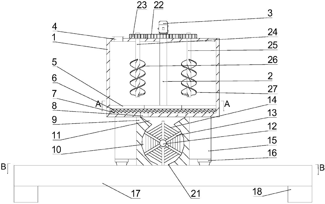
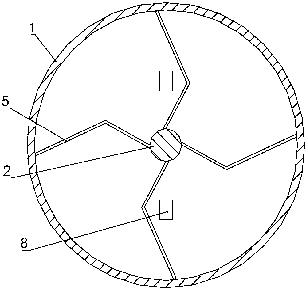
[0020] see Figure 1-3 , a concrete bridge surface paving device, comprising a moving material box 1, the inside of the moving material box 1 is provided with a rotating shaft 2, the top of the rotating shaft 2 passes through the upper side wall of the moving material box 1 and is connected with the moving material box 1 The upper side wall body of the upper side wall is connected in rotation, the upper side of the moving material box 1 is fixedly installed with a motor 3, the output end of the motor 3 is fixedly connected with the top of the rotating shaft 2, and the lower surface of the rotating shaft 2 is evenly and fixedly connected with several Bending plate 5, the lower part of bending plate 5 is evenly fixedly connected with No. 1 grinding protrusion 6, and the inner wall of the lower side of the moving material box 1 is evenly and fixedly c...


PUM


Abstract

The invention discloses a concrete bridge face aggregate laying device which comprises a moving material box. A first grinding protrusion at the lower portion of a bending plate and a second grindingprotrusion on the lower side wall body of the moving material box are used for rubbing so that bonding spheres in concrete aggregate are ground to be flat and are scattered, and a discharging port canbe hardly blocked by the concrete aggregate. When the concrete aggregate falls from the area between discharging plates, the concrete aggregates is impacted by a transverse steel wire to form an evenand loosened state. In the falling process of the concrete aggregate, the concrete aggregate is subjected to the third time of impacting through a vertical steel wire, and therefore uniformity and looseness of the concrete aggregate during falling are ensured. Due to the fact that a first spiral blade and a second spiral blade are opposite in spiral direction, the concrete aggregate flows from top to bottom through the first spiral blade, the concrete aggregate moves from bottom to top through the second spiral blade, cyclic circulation of the concrete aggregate is formed, and a very good homogenizing effect is achieved on the concrete aggregate.

Description

technical field [0001] The invention relates to the technical field of building construction, in particular to a concrete bridge surface paving device. Background technique [0002] At present, in the construction of highway bridges, whether it is prefabricated girders (including slab girders, T girders, small box girders and other types, etc.), or cast-in-place girders, the bridge deck is equipped with a leveling layer. In the construction of the bridge deck leveling layer, due to the characteristics of the bridge deck, the construction unit often uses a concrete delivery pump or a concrete tanker to directly drive the bridge deck steel mesh or steel bars for distribution. However, the two fabric methods often have the following defects: [0003] 1. Concrete delivery pumps are used for distribution, which can be divided into automobile pumps and ground pumps. Automobile pumps are fast in distributing and easy to move. However, when constructing bridge deck leveling layers...

Claims


Application Information

Patent Timeline
IPC IPC(8): E01D21/00E01C19/18E01D19/08
Inventor 王谋远
Owner 龙里县逸轩生产力促进中心
Why Eureka
Try Eureka