Heat dissipation structure of disc-type motor and disc-type motor

A disc motor and heat dissipation structure technology, applied in electrical components, electromechanical devices, electric components, etc., can solve the problems of difficult process realization, limited motor power, high production cost, and achieve obvious heat dissipation effect, suitable for mass production, and effective heat dissipation. Effect

Inactive Publication Date: 2018-01-16
仪坤动力科技(上海)有限公司
View PDF6 Cites 10 Cited by
  • Summary
  • Abstract
  • Description
  • Claims
  • Application Information

AI Technical Summary

Problems solved by technology

Obviously, this cooling structure has problems such as too complicated water channels, many structural components, easy to cause water leakage, high production cost, and difficult process realization.
[0005] The above-mentioned heat dissipation method mainly has the following disadvantages: 1. The heat at the end of the stator winding of the disc motor is mainly transferred to the casing through air convection, without considering how the end of the stator winding conducts heat efficiently with the casing, which limits the power of the motor (mainly for ordinary heat sinks); 2. The cooling structure is too complex to be mass-produced; 3. In order to achieve the cooling effect, multiple cooling water channels are designed, and there is no optimal design of the heat dissipation structure from the perspective of the system
[0006] To sum up, the existing heat dissipation structure of disc motors has problems of either complex structure or irrational heat dissipation effect

Method used


Image

  • Heat dissipation structure of disc-type motor and disc-type motor
  • Heat dissipation structure of disc-type motor and disc-type motor
  • Heat dissipation structure of disc-type motor and disc-type motor

Examples


Embodiment Construction

[0035] The following will clearly and completely describe the technical solutions in the embodiments of the present invention with reference to the accompanying drawings in the embodiments of the present invention. Obviously, the described embodiments are only part of the embodiments of the present invention, not all of them. Based on the embodiments of the present invention, all other embodiments obtained by persons of ordinary skill in the art without creative efforts fall within the protection scope of the present invention.

[0036] It should be noted that if there is a directional indication (such as up, down, left, right, front, back...) in the embodiment of the present invention, the directional indication is only used to explain the position in a certain posture (as shown in the accompanying drawing). If the specific posture changes, the directional indication will also change accordingly.

[0037] In addition, if there are descriptions involving "first", "second" and ...


PUM


Abstract

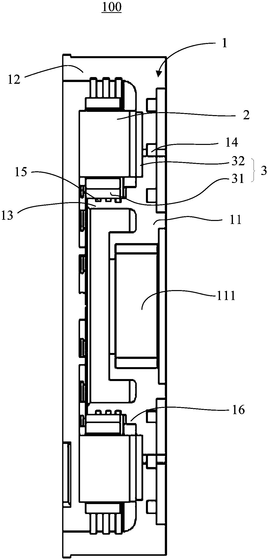
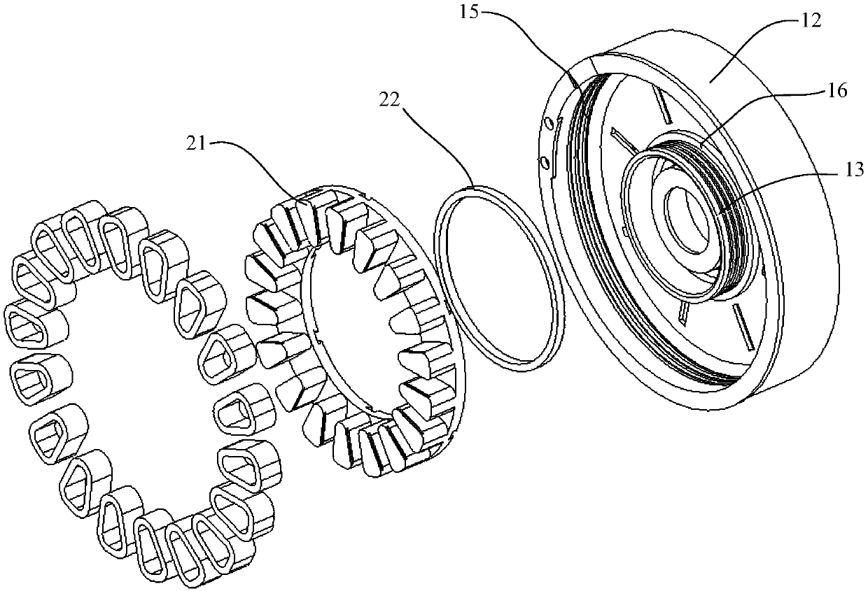
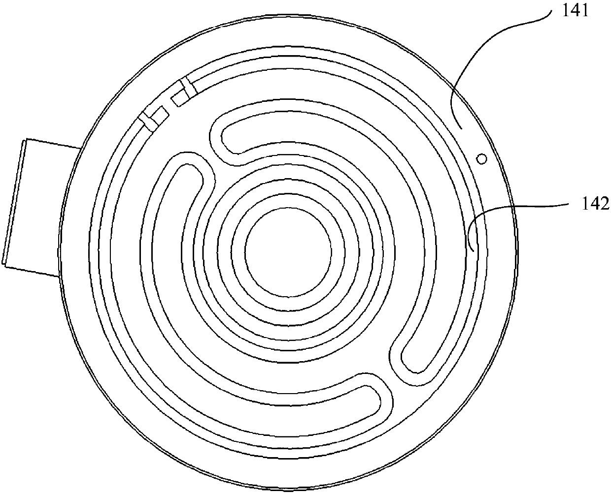
The invention discloses a heat dissipation structure of a disc-type motor and the disc-type motor. The heat dissipation structure of the disc-type motor comprises an end cover, a stator assembly, a first heat conduction glue layer and a cooling structure, wherein a first end cover comprises a bottom plate and an annular side plate, a via hole is formed in the bottom plate, an annular installationbulge is further arranged on an inner surface of the end cover in a protruding way and encircles the via hole, a first cooling passage is arranged in the first end cover, the stator assembly is arranged in the first end cover and sleeves the annular installation bulge, and heat conduction glue is filled between the stator assembly and an inner wall surface of the first end cover and is used for transferring heat of the stator assembly to a first cooling passage of the end cover. By the heat dissipation structure, effective heat dissipation of the heat dissipation structure of the disc-type motor is achieved, the heat dissipation structure is simple and obvious in heat dissipation effect, a traditional mode employing a large amount of screws to fasten is overcome, the process is greatly simplified, and the heat dissipation structure is very suitable for mass production.

Description

technical field [0001] The invention relates to the technical field of disk motors, in particular to a heat dissipation structure of a disk motor and a disk motor. Background technique [0002] Disc motors have the characteristics of small size, light weight, and high power density. Cooling and thermal design are important issues to be solved for disc motors. There are basically two traditional solutions. One is the air-cooled structure, which uses air-cooled cooling fins outside the motor end cover. This method has poor appearance and weak heat dissipation, which limits the power increase of the motor; the other is the cooling structure. For details, see Cases of public information below. [0003] Prior Art 1 (Patent No.: 2012104671400) discloses a cooling structure, which adopts a base (including a water tank) and an end cover to seal to form a gear-shaped water-cooling pipe. The water flow resistance of the pipe in this way is relatively large, and a sealing ring is requ...

Claims


Application Information

Patent Timeline
Patent Type & Authority Applications(China)
IPC IPC(8): H02K5/20H02K9/22
Inventor 张景程焦伟
Owner 仪坤动力科技(上海)有限公司
Why Eureka
Try Eureka