Permanent-magnet switch reluctance motor with axially-magnetized rotor

A permanent magnet switch, axial magnetization technology, applied in electrical components, electromechanical devices, magnetic circuit static parts, etc., can solve the problems of motor magnetic energy expansion limitation, difficulty in implementing magnetic isolation measures, affecting the structural strength of the motor, etc. Simple and reliable installation, wide electromagnetic energy conversion area and large number of magnetic poles

Pending Publication Date: 2018-01-16
SHIDAI IND AUTOMATION
View PDF7 Cites 4 Cited by
  • Summary
  • Abstract
  • Description
  • Claims
  • Application Information

AI Technical Summary

Problems solved by technology

At present, the permanent magnet installation methods used in most permanent magnet switched reluctance motors adopt the surface mount method and the built-in method. The permanent magnets are distributed in various installation positions, and the manufacturing process is complicated. The corresponding magnetic isolation measures are difficult to implement and affect the structural strength of the motor. The utilization rate of magnetic energy is low, and the expansion of motor magnetic energy is limited

Method used


Image

  • Permanent-magnet switch reluctance motor with axially-magnetized rotor
  • Permanent-magnet switch reluctance motor with axially-magnetized rotor
  • Permanent-magnet switch reluctance motor with axially-magnetized rotor

Examples


Embodiment Construction

[0033] The present invention will be further described below with reference to the accompanying drawings and embodiments.

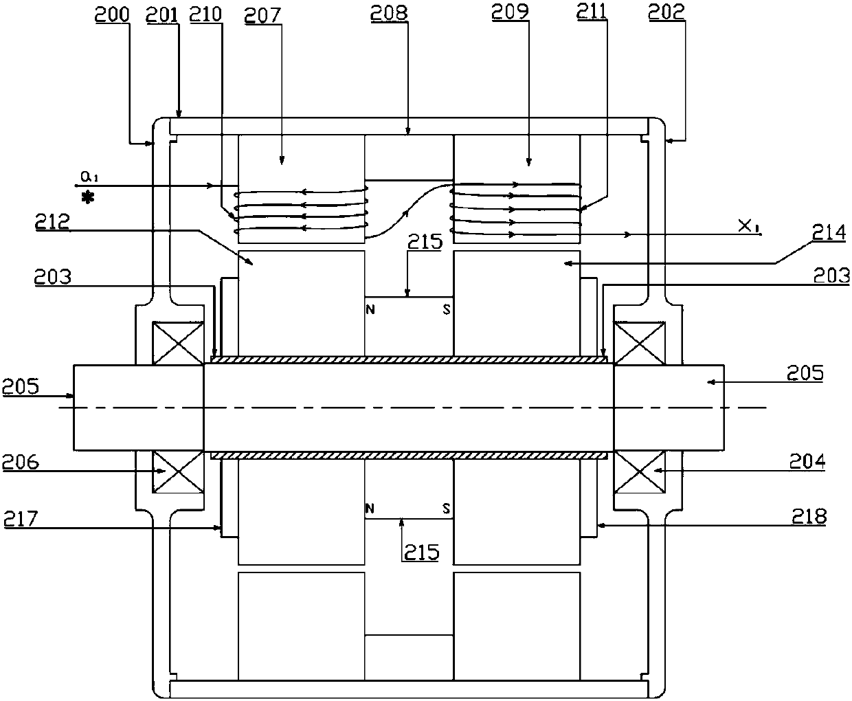
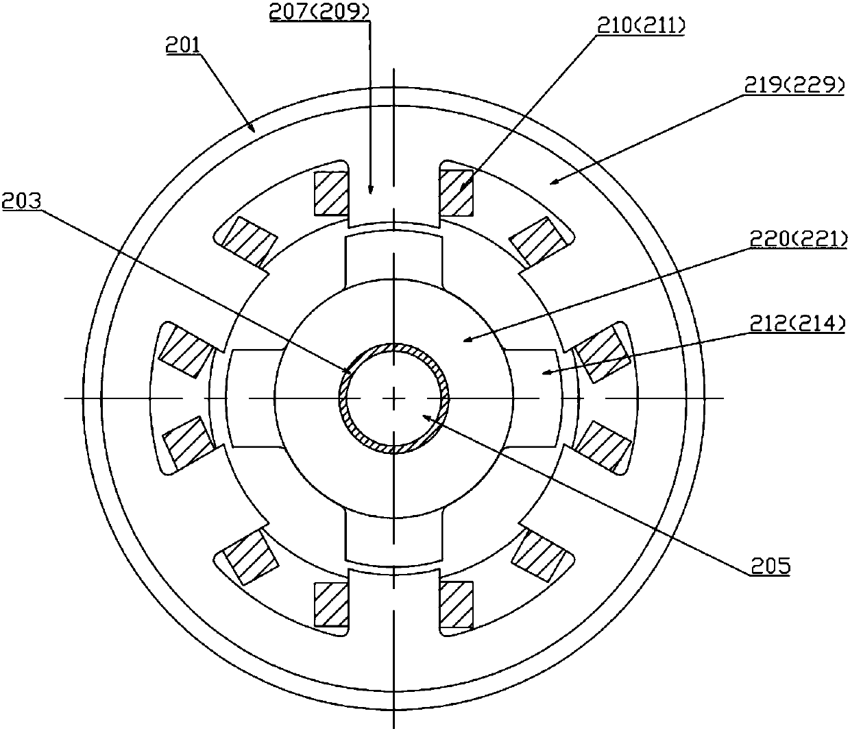
[0034] like Figure 1-Figure 4 As shown, the present invention includes a motor housing 201, a stator and a rotor. The motor housing 201 is fixed on the machine base by fixing screw holes and bolts. The motor housing 201 is provided with a left end cover 200 and a right end cover 202 at both ends, and the right end cover 202 is provided with a rotor. A position sensor is used to detect the position of the rotor; the stator includes a left-segment stator core 224, a right-segment stator core 225 and an inter-segment yoke 208 embedded between the left and right stator cores with the same structure. The yoke 208 connects the left and right stator cores to form a two-segment integral stator.

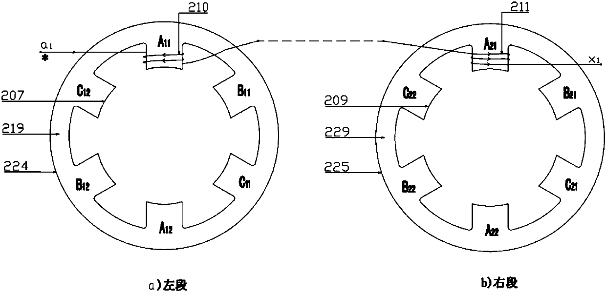
[0035] The left stator core 224 includes the left stator yoke 219 and the left stator magnetic poles 207 distributed on the inner ring of the stator left yoke 219, and...


PUM


Abstract

The invention discloses a permanent-magnet switch reluctance motor with an axially-magnetized rotor. The permanent-magnet switch reluctance motor comprises a motor shell, a stator and the rotor, wherein the motor shell is fixed on an engine base, a left end cover and a right end cover are arranged at two ends of the motor shell, the stator comprises a left segment of stator core, a right segment of stator core and an intersegment magnetic yoke, the left segment of stator core and the right segment of stator core have same structures, the intersegment magnetic yoke is arranged between the two segments of stator core, the left segment of stator core and the right segment of stator core are connected to the whole stator by the intersegment magnetic yoke, the motor rotor comprises a rotor shaft, a magnetic isolation lining sleeve, a left segment of rotor core, a left segment of rotor core and a permanent-magnet cylinder, the left segment of rotor core and the right segment or rotor core have same structures, the permanent-magnet cylinder is arranged between the two segments of rotor core and is axially magnetized, the left end cover and the right end cover are connected with a left extension end and a right extension end of the rotor shaft via bearings, the magnetic isolation lining sleeve sleeves the rotor shaft in a fastening way, and the left segment of rotor core, the permanent-magnet cylinder and the right segment of rotor core sequentially sleeve the magnetic isolation lining sleeve in a matching way. The permanent magnet is simple and reliable to install and is good in magnetic isolation effect, many magnetic poles are involved during running of the motor in a working condition, the electromagnetic energy conversion area is wide, the efficiency is high, and power density is large.

Description

technical field [0001] The invention relates to the field of motors, in particular to a rotor axially magnetized permanent magnet switched reluctance motor. Background technique [0002] Switched reluctance motor is a kind of motor with double salient poles of stator and rotor, which uses the principle of reluctance to generate drag torque and realize the conversion of electrical energy into mechanical energy. Switched reluctance motor stator poles are wound with concentrated windings, and there are no windings or permanent magnets on the rotor. The motor structure is simple and reliable. The armature windings of switched reluctance motors usually use single-phase armature windings for power supply. The number of magnetic poles is small and the magnetic energy area is small, which limits the power density of the motor. The three-phase and more than three-phase reluctance motor drives have high cost and large mechanical noise. The permanent magnet switched reluctance motor ha...

Claims


Application Information

Patent Timeline
Patent Type & Authority Applications(China)
IPC IPC(8): H02K16/02H02K1/14H02K1/27H02K3/28H02K29/06
Inventor 黄运生蒋湘君许跃峰陈东豪
Owner SHIDAI IND AUTOMATION
Why Eureka
Try Eureka