Punching device

A technology of stamping device and stamping die, applied in the direction of feeding device, positioning device, storage device, etc., can solve the problems of blockage of stamping parts, affecting the dimensional accuracy of stamping, difficult operation, etc., and achieve the effect of high stamping efficiency and less power devices

Inactive Publication Date: 2018-01-19
象山信基机械厂
View PDF7 Cites 8 Cited by
  • Summary
  • Abstract
  • Description
  • Claims
  • Application Information

AI Technical Summary

Problems solved by technology

[0004] However, there are still certain problems in the above-mentioned technical solution: the plate debris generated during the stamping process is easy to deposit in the punching hole, which affects the dimensional accuracy of subsequent stamping. difficult to remove

Method used


Image

  • Punching device

Examples


Embodiment Construction

[0017] The present invention will be described in further detail below by means of specific embodiments:

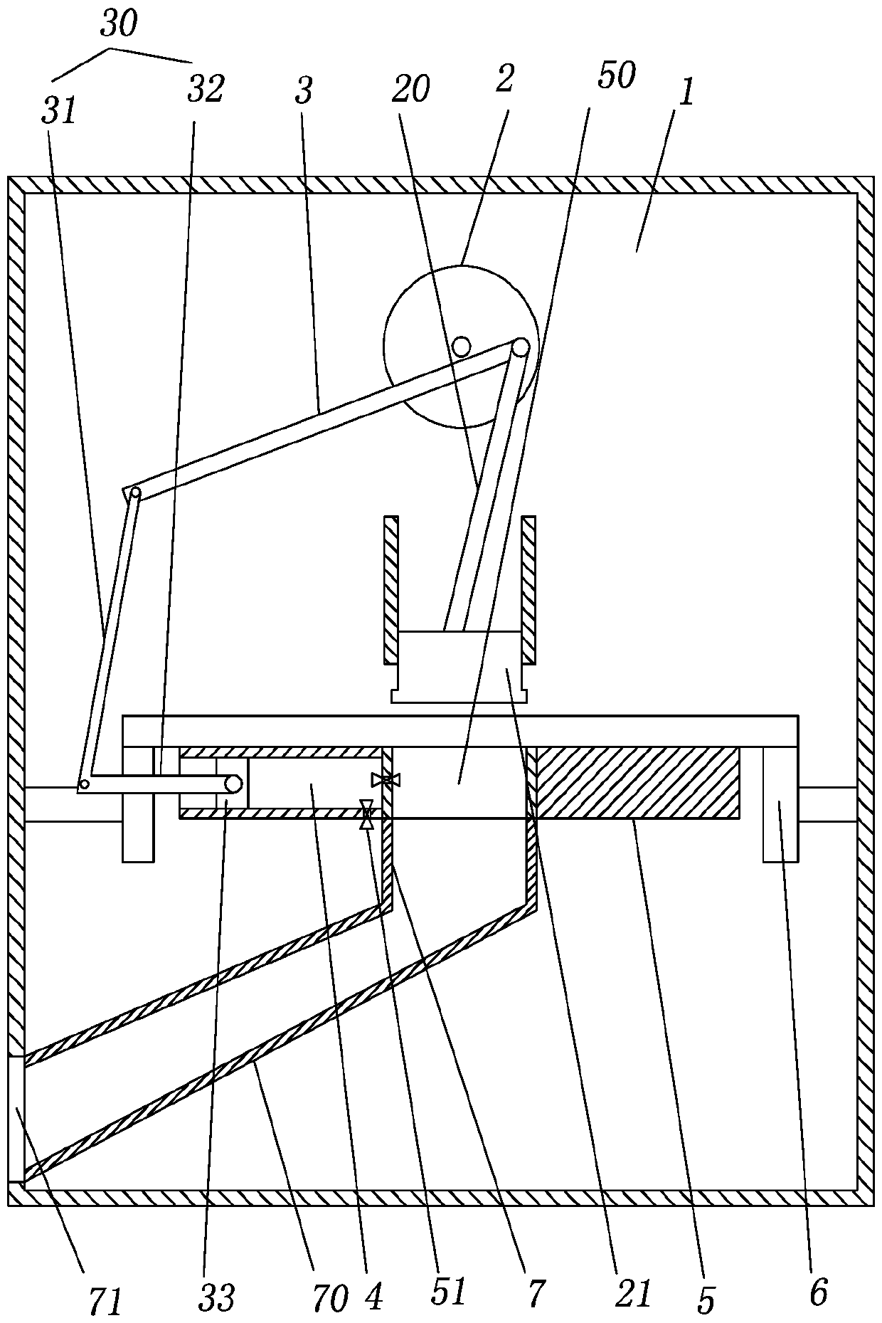
[0018] The reference signs in the drawings of the description include: stamping box 1, crank 2, stamping rod 20, stamping head 21, swing rod 3, blowing rod 30, first rod 31, second rod 32, piston 33, sliding cavity 4 , stamping die 5, stamping hole 50, one-way valve 51, conveying roller 6, straight pipe 7, inclined pipe 70, discharge port 71.

[0019] The embodiment is basically as attached figure 1 Shown: stamping device, including motor, stamping die 5, stamping box 1 and stamping head 21 located above stamping die 5, stamping die 5 is provided with punching hole 50, also includes power mechanism, blowing mechanism and for conveying steel plate The conveying mechanism; the power mechanism includes a crank 2 and a stamping rod 20, the output shaft of the motor is connected to the crank 2, one end of the stamping rod 20 is hinged to the crank 2, the other end of the stam...


PUM


Abstract

The invention relates to the technical field of rigidity piece punching, in particular to a punching device. The punching device comprises a motor, a punching die, a punching box and a punching head.A punching hole is formed in the punching die. The punching device further comprises a power mechanism, an air blowing mechanism and a conveying mechanism for conveying steel plates. The power mechanism comprises a crank and a punching rod. An output shaft of the motor is connected with the crank, one end of the punching rod is hinged to the crank, the other end of the punching rod is hinged to the punching head, and the punching head is in sliding connection into the punching box. The air blowing mechanism comprises a swinging rod, an air blowing rod and a piston, a sliding cavity is formed in the punching die, the sliding cavity is provided with an air inlet pipe for air inflow and an air outlet pipe for air outflow, each of the air inlet pipe and the air outlet pipe is provided with a one-way valve, and the air outlet pipe is aligned with the punching hole. By adoption of the technical scheme, scraps at the position of the punching hole can be cleaned away, and it is guaranteed thatpunching is smoothly conducted.

Description

technical field [0001] The invention relates to the technical field of stamping of rigid parts, in particular to a stamping device. Background technique [0002] Stamping is a forming processing method that applies external force to plates, strips, pipes and profiles by presses and molds to cause plastic deformation or separation to obtain workpieces (stamping parts) of required shape and size. Stamping and forging belong to plastic processing (or pressure processing) and are collectively called forging. The blanks for stamping are mainly hot-rolled and cold-rolled steel sheets and strips. Among the steel products in the world, 60-70% are plates, most of which are stamped into finished products. During the stamping process, traditional stamping machines can only stamp one type and specification of stamping parts, which seriously wastes the efficiency of stamping equipment. [0003] The Chinese patent with the notification number CN206229899U discloses a stamping machine, ...

Claims


Application Information

Patent Timeline
Patent Type & Authority Applications(China)
IPC IPC(8): B21D28/26B21D28/34B21D45/04B21D43/08
Inventor 王健
Owner 象山信基机械厂
Why Eureka
Try Eureka