Centering device for steel tube welding

A centering device and steel pipe technology, applied in the field of steel pipes, can solve the problems of poor control of cutting angle, time-consuming and labor-intensive cutting, etc., and achieve the effects of manpower saving, convenient welding and simple operation

Inactive Publication Date: 2018-01-19
NANJING AIFENG TECH CO LTD
View PDF0 Cites 0 Cited by
  • Summary
  • Abstract
  • Description
  • Claims
  • Application Information

AI Technical Summary

Problems solved by technology

[0002] In the field of steel pipes, it is necessary to weld two steel pipes of different lengths together. During the welding process, the two steel pipes need to be centered. In traditional welding, one heats the two steel pipes against each other, and the other person welds them again, especially When welding two steel pipes at an angle, the welding process is cumbersome. In the past, the welder lay down on the ground and checked whether the two pipes wer

Method used


Image

  • Centering device for steel tube welding
  • Centering device for steel tube welding

Examples


Example Embodiment

[0014] Below in conjunction with accompanying drawing and specific embodiment the present invention is described in further detail:

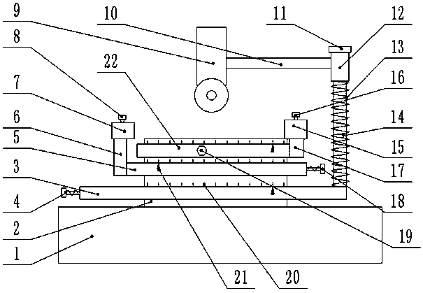
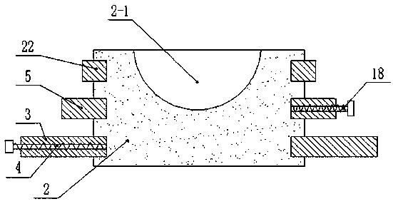
[0015] like Figure 1-2 As shown, a steel pipe welding centering device includes a bottom plate 1, a worktable 2 is fixed on the upper part of the bottom plate 1, an arc-shaped groove 2-1 is provided on the upper surface of the workbench 2, and the workbench 2 is a cylinder Shaped, the outer ring of the workbench 2 is provided with three grooves at intervals, and the three grooves of the workbench 2 from bottom to top are respectively rotatably connected with an annular ring A3, an annular ring B5 and an annular ring C22. The side ends of the ring A3, the annular ring B5 and the annular ring C22 are screwed with the set screw A4, the set screw B18, and the set screw C19 respectively, and the side end of the annular ring B5 is fixed with a vertical pole A6, and the pole A6 A sleeve A7 is fixed on the sleeve A7, and a locking screw A8 is screwed ...


PUM


Abstract

The invention discloses a centering device for steel tube welding. The device comprises a bottom plate, wherein a workbench is fixed on the upper part of the bottom plate; an arc-shaped groove is formed in the upper surface of the workbench; the workbench is cylindrical; three grooves are formed in the outer ring of the workbench at intervals; the three grooves from bottom to top of the workbenchare rotationally connected with an annular ring A, an annular ring B and an annular ring C respectively; the side end of the annular ring A is in threaded connection with a fixing screw A, the side end of the annular ring B is in threaded connection with a fixing screw B, and the side end of the annular ring C is in threaded connection with a fixing screw C; a supporting rod A perpendicular to theannular ring B is fixed at the side end of the annular ring B; a sleeve A is fixed on the supporting rod A; the sleeve A is in threaded connection with a locking screw A; and a supporting rod B perpendicular to the annular ring C is fixed at the side end of the annular ring C. According to the centering device for steel tube welding, the centering angle of two steel tubes is accurately controlled, more convenience is brought to the welding process, centering of the steel tubes is more accurate, operation is simpler, and the labor is saved; and the cutting angle of the head of the steel tube is better controlled, cutting is relatively convenient, and the welding speed of the steel tubes is improved.

Description

technical field [0001] The invention relates to the field of steel pipes, in particular to a steel pipe welding centering device. Background technique [0002] In the field of steel pipes, it is necessary to weld two steel pipes of different lengths together. During the welding process, the two steel pipes need to be centered. In traditional welding, one heats the two steel pipes against each other, and the other person welds them again, especially When welding two steel pipes at an angle, the welding process is cumbersome. In the past, the welder lay down on the ground and checked whether the two pipes were skewed when connecting two pipes. The environment is unfavorable, it is difficult for us to find a relatively flat ground, and it requires two people to operate at the same time, which is time-consuming and laborious. When the two steel pipes to be welded form a certain angle, it is necessary to additionally cut the head of the steel pipe to form a certain angle, and Th...

Claims


Application Information

Patent Timeline
IPC IPC(8): B23K37/053B23K101/06
Inventor 王爱兵
Owner NANJING AIFENG TECH CO LTD
Why Eureka
Try Eureka