A variable arc mechanism

A variable, arc technology, applied in the direction of metal processing mechanical parts, manufacturing tools, workpiece clamping devices, etc., can solve the problems of processing, profiling, and clamping cannot be carried out effectively and efficiently, and achieve high arc accuracy, Good stability and the effect of improving arc accuracy

Active Publication Date: 2019-09-10
SOUTH CHINA AGRI UNIV
View PDF7 Cites 0 Cited by
  • Summary
  • Abstract
  • Description
  • Claims
  • Application Information

AI Technical Summary

Problems solved by technology

Most of the research and inventions still stay at the level where the exterior is the executive part and the core is the solid machine, which makes it impossible to effectively and efficiently perform machining, profiling, and clamping on the outer surfaces of shafts and arcs. conduct

Method used


Image

  • A variable arc mechanism
  • A variable arc mechanism
  • A variable arc mechanism

Examples


Embodiment 1

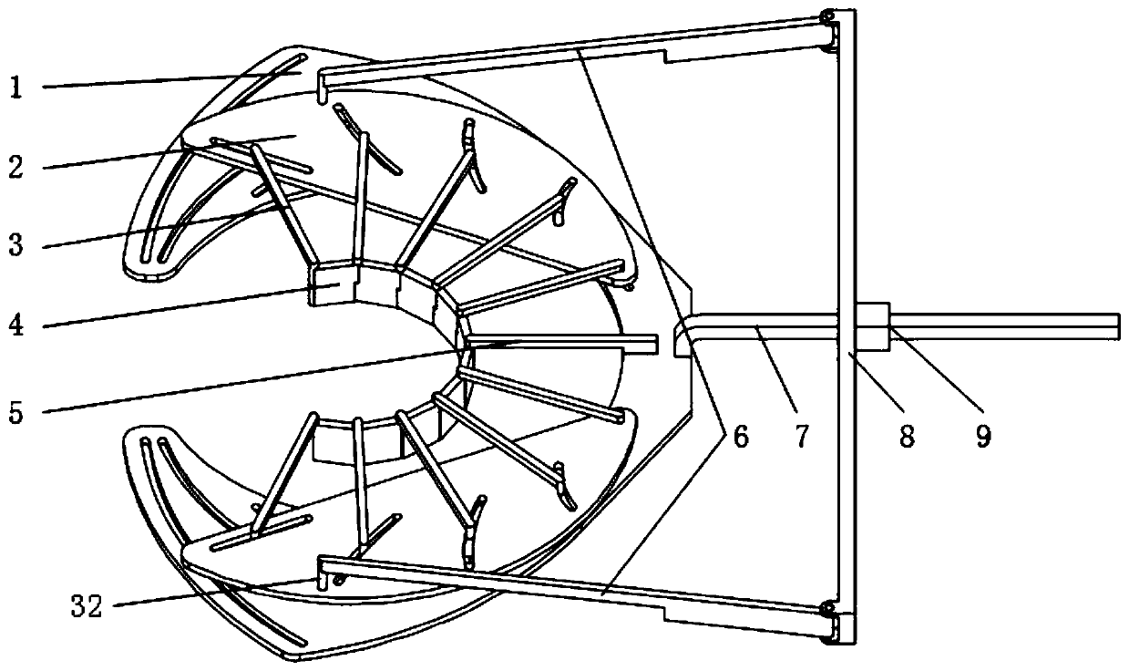
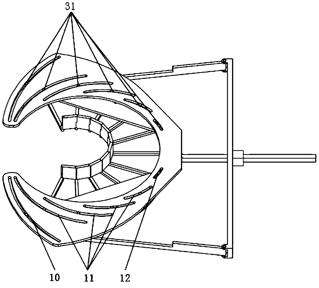
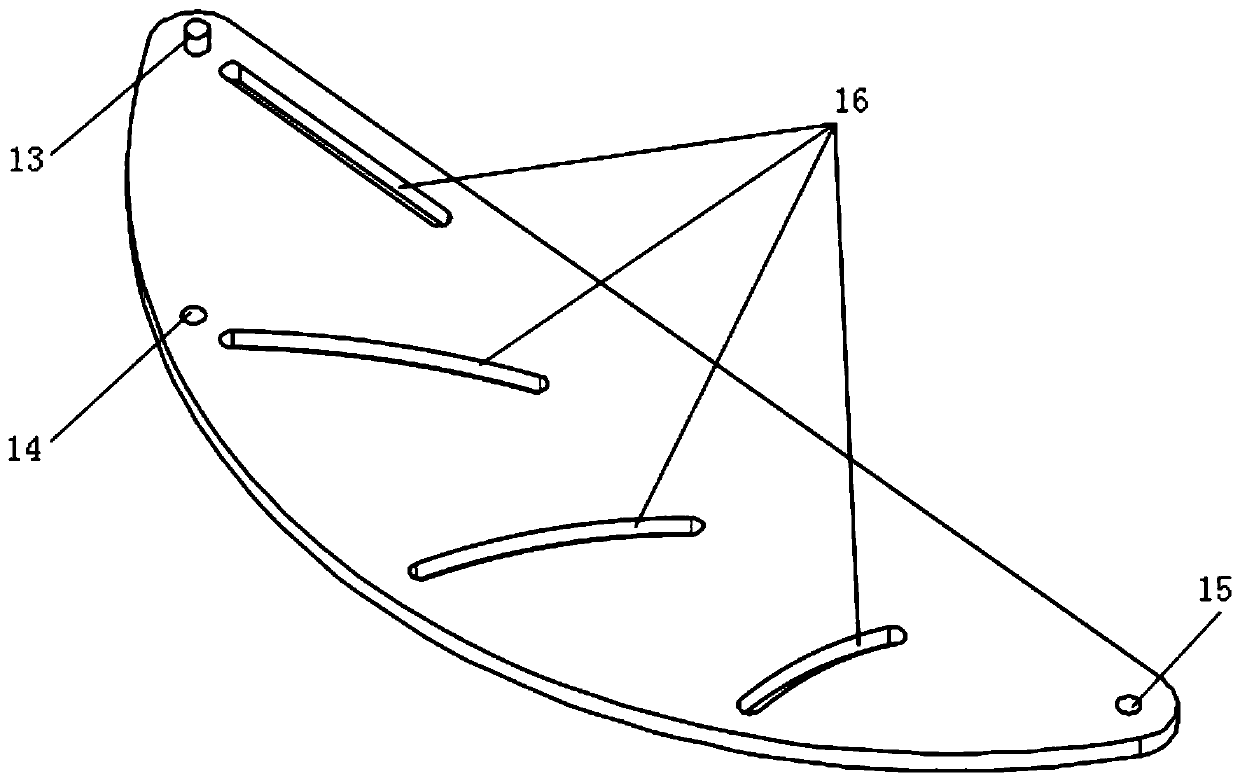
[0026] see Figure 1 to Figure 3As shown, the variable arc mechanism described in this embodiment includes an actuating part and a driving part, and the actuating part includes a fixed slide 1, a moving slide 2, a dynamic variable arc support rod 3, and a rigid arc 4 , fixed and variable arc support rod 5, the driving part includes a driving transmission rod 6, a moving pair guide rod 7, a driving push rod 8, and a moving pair slider 9; the fixed sliding plate 1 is designed as a jaw structure, and The left and right parts are mirror images, and each part is formed with a first chute (specifically an arc-shaped trough) distributed along its respective shape trajectory, and the length of the first chute gradually decreases from the opening of the jaw, that is, close to the The first chute at the opening of the jaw is the longest, which is 10 shown in the figure, and the first chute near the tail of the jaw is the shortest, which is 12 shown in the figure, and 11 shown in the fig...

Embodiment 2

[0029] The difference from Embodiment 1 is that in this embodiment, the fixed variable arc support rod 5 is replaced by a dynamic variable arc support rod (not shown in the figure), so that the variable arc can obtain a degree of freedom, that is, along the circle The degree of freedom of rotation in the direction of rotation of the arc center, so that high arc accuracy, high rotation radius accuracy, high stability and high adaptability can be performed within a small rotation range, so that the arc can change its radius statically and dynamically Movement along an arc is possible.

Embodiment 3

[0031] The difference from Embodiment 1 is that the support rod of this embodiment only retains the dynamic and variable arc support rod 3 that cooperates with the movable slide, instead of using the fixed and variable arc support rod 5, that is, at the tail of the fixed slide 1 Support rod (not shown in the figure) is installed no longer in the center.

[0032] To sum up, the whole mechanism of the present invention can complete the variable diameter adjustment of the circular arc formed by the rigid arcs during the movement of the moving sub-slider 9, realizing the possibility of taking the outside as an entity and the center as a hollow. The research and development of the variable arc mechanism has achieved the purpose of variable control of the arc. The movable secondary guide rod and the fixed sliding piece of the mechanism can be fixed together in many different ways, and can also be processed as a whole in the same piece of material, and the production cost is low. In...


PUM


Abstract

The invention discloses a variable circular arc mechanism comprising fixed sliding pieces, movable sliding pieces, movable variable circular arc supporting rods, a rigid arc piece, a movable pair guiding rod, a movable pair sliding block, a driving pushing rod and driving transmission rods. The mechanism is divided into two functional parts of the executive part and the driving part. According tothe mechanism, the radian and radius of a circular arc are changed mainly through the mode that the fixed sliding pieces and the movable sliding pieces are matched with sliding grooves to drive terminal executive parts, in the rotating process of the movable pair sliding block, variable diameter adjustment of the circular arc composed of the rigid arc piece can be completed, research and development of the variable circular arc mechanism with the exterior as the entity and the core being hollow are achieved, and the purpose of variable control over the circular arc is achieved. The variable circular arc mechanism is small in overall size, simple in structure, easy to control, high in reliability, high in circular arc precision, large in variable diameter range, wide in application range and low in energy consumption cost.

Description

technical field [0001] The invention relates to the technical field of agricultural machinery, in particular to a variable arc mechanism. Background technique [0002] At present, the research on the variable arc mechanism with a solid exterior and a hollow center is still blank at home and abroad. Most of the research and inventions still stay at the level where the exterior is the executive part and the core is the solid machine, which makes it impossible to effectively and efficiently perform machining, profiling, and clamping on the outer surfaces of shafts and arcs. conduct. Therefore be badly in need of developing the novel variable arc mechanism that the inside is hollow and the outside is solid. Contents of the invention [0003] The purpose of the present invention is to overcome the deficiencies of the prior art and provide a variable arc mechanism with simple structure, wide adaptability, easy control, and high reliability, mainly for the external surfaces of ...

Claims


Application Information

Patent Timeline
Patent Type & Authority Patents(China)
IPC IPC(8): B23Q3/06B25B11/00
Inventor 杨洲许泽宇段洁利金莫辉孙健峰郭杰
Owner SOUTH CHINA AGRI UNIV
Why Eureka
Try Eureka