A convenient mechanical parts processing equipment and using method

A technology for mechanical parts and processing equipment, applied in the field of mechanical parts processing, can solve the problems of generating a large amount of waste, damage to processing equipment, adverse effects on the working environment and users, and achieves improved cleaning quality, improved work efficiency, and achieved The effect of non-stop continuous operation

Active Publication Date: 2021-07-27
浙江汇丰汽车零部件股份有限公司
View PDF7 Cites 0 Cited by
  • Summary
  • Abstract
  • Description
  • Claims
  • Application Information

AI Technical Summary

Problems solved by technology

[0003] When the existing commonly used plate-shaped or rectangular mechanical parts are processed by processing equipment, a large amount of waste will be generated, and some processing equipment will also generate exhaust gas when processing mechanical parts, while the existing processing equipment The inability to effectively treat exhaust gas and waste chips will cause many adverse effects on the working environment and users. At the same time, it will easily cause damage to the processing equipment, resulting in a short service life of the processing equipment, and at the same time, some waste chips remain on the outer wall of the mechanical parts. , it also needs to be manually cleaned regularly, which increases the labor burden and leads to poor processing quality of mechanical parts. Therefore, we propose a convenient-to-use mechanical parts processing equipment and its use method

Method used


Image

  • A convenient mechanical parts processing equipment and using method
  • A convenient mechanical parts processing equipment and using method
  • A convenient mechanical parts processing equipment and using method

Examples


Embodiment 1

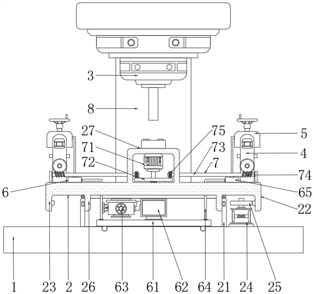
[0024] Embodiment 1: An easy-to-use mechanical parts processing equipment, please refer to 1, including base 1 and processing equipment main body 3, processing equipment main body 3 is widely used in this field, and its structure and principle are well known to those skilled in the art , those skilled in the art can choose flexibly, and will not be described in detail here. The electrical components appearing in the present invention are all connected to the external main controller and 220V mains, and the main controller can be controlled by a computer, etc. Conventional known equipment, specifically, a battery is fixed on the top of the installation shell 27, and the servo motor 71 and the servo motor 46 are both electrically connected to the battery, so that the rotation of the workbench 22 will not affect its use;

[0025] Please refer to 1. There is a continuous operation table 2 on the top of the base 1. The continuous operation table 2 is convenient for fixing multiple s...

Embodiment 2

[0031] Embodiment 2: This embodiment is different from the above embodiment, please refer to figure 1 The continuous operation workbench 2 includes a receiving shell 21 fixed at the center of the top of the base 1. The receiving shell 21 is located in front of the mounting frame 8. The receiving shell 21 is cylindrical. The top and bottom of the receiving shell 21 are open. The front of the receiving shell 21 A shell cover (not shown) is provided on the side to facilitate maintenance of the structure in the receiving shell 21. A workbench 22 is arranged above the accepting shell 21. The workbench 22 plays the role of supporting and installing the structure. The bottom of the workbench 22 is from the outside to the outside. An annular flange 1 23 and an annular flange 2 26 are integrally formed inside in turn, the outer wall of the annular flange 2 26 fits the inner wall of the receiving shell 21, and the outer walls of the left and right sides of the annular flange 2 26 are sym...

Embodiment 3

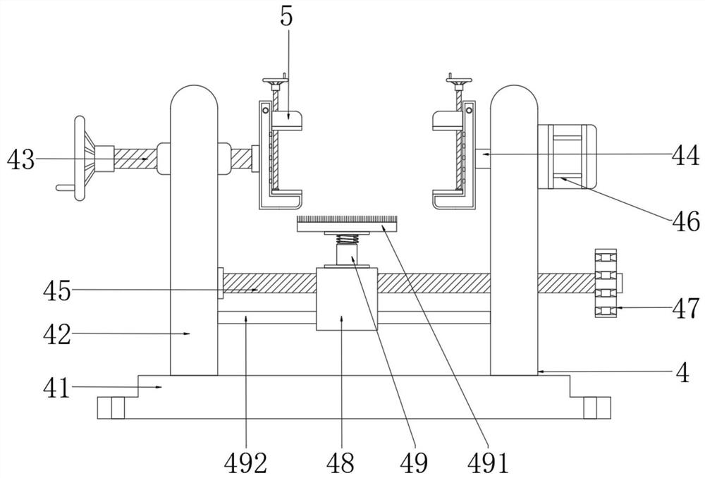
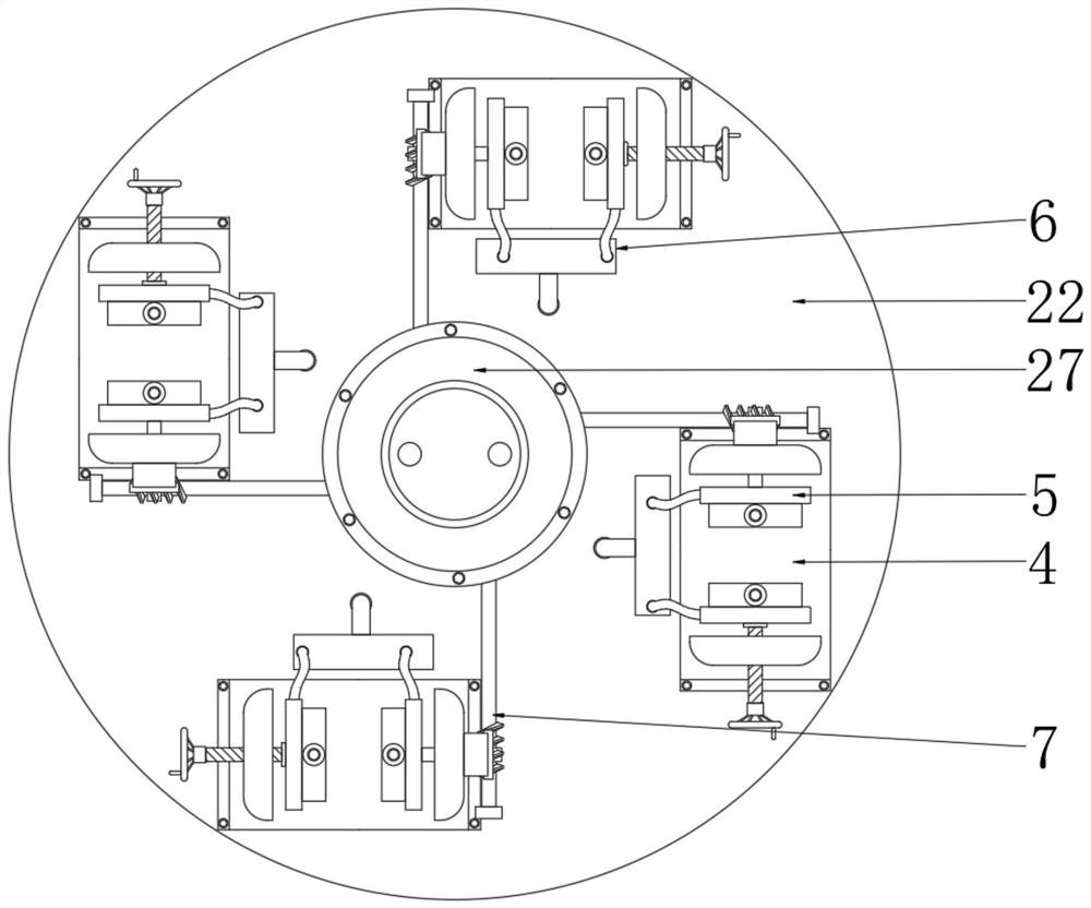
[0032] Embodiment 3: The difference between this embodiment and the above-mentioned embodiment is that please refer to Figure 1-Figure 3 , (Here, the frontmost part accepts the cleaning mechanism 4 as a supporting illustration, and the other three groups of parts accept the cleaning mechanism 4 with the same structure, but the corresponding changes in position will not be described in detail here) Four The parts receiving and cleaning mechanism 4 is arranged in an annular array on the top of the workbench 22. The parts receiving and cleaning mechanism 4 includes a fixed plate 41 fixed on the top of the workbench 22. The fixed plate 41 can be fixed on the workbench 22 by means of screws or bolts. The top, the left and right sides of the top of the fixed plate 41 are fixedly provided with a support plate 42, the support plate 42 plays the role of support and installation structure, the top left and right threads of the left support plate 42 are provided with an adjusting screw 4...


PUM


Abstract

The invention discloses a convenient-to-use mechanical parts processing equipment in the technical field of mechanical parts processing, comprising a base and a processing equipment main body, a continuous operation workbench is arranged on the top of the base, and an annular array is arranged on the top of the continuous operation workbench There are four groups of parts receiving and cleaning mechanisms with the same structure. The parts receiving and cleaning mechanisms of the four groups are symmetrically equipped with clamping and removing chips with the same structure. Connected chip removal mechanism, the present invention is equipped with a chip removal mechanism, the exhaust fan will extract the air in the dust collection case, and the exhaust gas sucked in will be purified by the influence of the filter plate in the dust collection case, so that the sucked waste chips, etc. will be filtered The plate block remains in the dust collection case, reducing the impact on the working environment and staff while avoiding damage to the main body of the processing equipment, and at the same time improving the cleaning quality of the parts by the subsequent cooperation of the connecting drive mechanism and the parts receiving and cleaning mechanism.

Description

technical field [0001] The invention relates to the technical field of mechanical parts processing, in particular to a conveniently used mechanical parts processing equipment and a use method. Background technique [0002] Mechanical parts, also known as mechanical components, are the basic components of machinery, and are inseparable individual parts that make up machinery and machines. Mechanical parts are not only a subject of research and design of mechanical basic parts in various equipment, but also a general term for parts and components. In the process of producing mechanical parts, processing equipment is often required to process them. Common processing equipment includes grinding , punching and welding etc. [0003] When the existing commonly used plate-shaped or rectangular mechanical parts are processed by processing equipment, a large amount of waste will be generated, and some processing equipment will also generate exhaust gas when processing mechanical part...

Claims


Application Information

Patent Timeline
Patent Type & Authority Patents(China)
IPC IPC(8): B23Q11/00B23Q3/06B23Q1/25
CPCB23Q1/25B23Q3/06B23Q11/0046
Inventor 李文龙
Owner 浙江汇丰汽车零部件股份有限公司
Why Eureka
Try Eureka