Eureka AIR delivers breakthrough ideas for toughest innovation challenges, trusted by R&D personnel around the world.

Manual release device for air brake

A technology of air brake and connecting device, which is applied in the railway brake system, the operating mechanism of the brake of the railway vehicle, transportation and packaging, etc., and can solve the problems of potential safety hazards, inconvenient, dangerous, etc.

Active Publication Date: 2018-01-19
CRRC TANGSHAN CO LTD
View PDF10 Cites 7 Cited by
  • Summary
  • Abstract
  • Description
  • Claims
  • Application Information

AI Technical Summary

Problems solved by technology

[0003] Generally, the manual relief valve of the train is designed under the train. If the train breaks down during operation and needs to be manually relieved, the driver needs to get off the train to work on the ground. Sometimes it is difficult for the driver to approach the manual relief valve for manual relief operation, which is not very convenient.
At the same time, when the driver works on the ground, he is very close to the opposite train, which poses a safety hazard. Especially for trains powered by the third rail, the driver is very close to the third rail with high-voltage electricity when working on the ground, which is very dangerous.

Method used


Image

  • Manual release device for air brake
  • Manual release device for air brake
  • Manual release device for air brake

Examples


Embodiment Construction

[0058] In order to make the purpose, technical solutions and advantages of the embodiments of the present invention clearer, the technical solutions in the embodiments of the present invention will be clearly and completely described below in conjunction with the drawings in the embodiments of the present invention. Obviously, the described embodiments It is a part of embodiments of the present invention, but not all embodiments. Based on the embodiments of the present invention, all other embodiments obtained by persons of ordinary skill in the art without creative efforts fall within the protection scope of the present invention.

[0059] In describing the present invention, it should be understood that the terms "upper", "lower", "front", "rear", "left", "right", "axial", "peripheral" and the like indicate directions or The positional relationship is based on the orientation or positional relationship shown in the drawings, which is only for the convenience of describing th...


PUM


Abstract

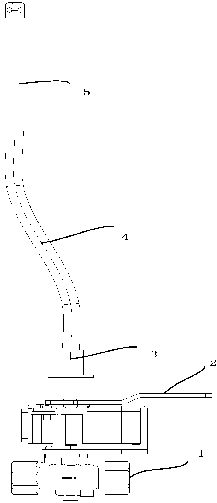
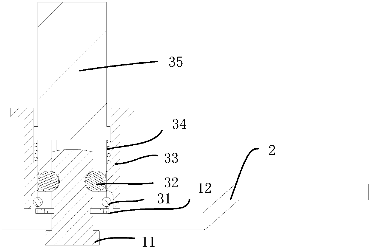
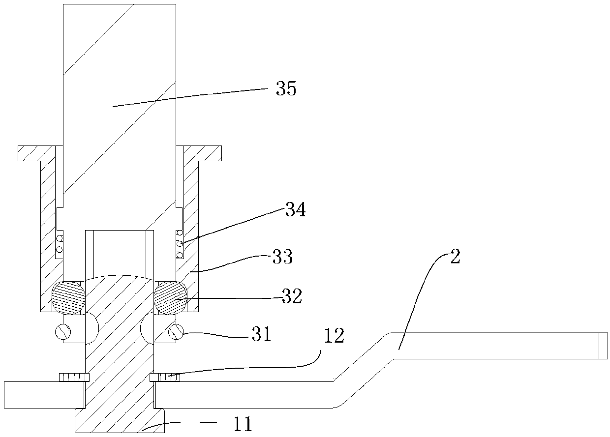
The embodiment of the invention provides a manual release device for an air brake. The manual release device comprises a cut-out cock, a first operation handle, a flexible shaft and two connection devices, wherein the cut-out cock is provided with a first rotating rod; the first end of the first rotating rod is connected with a valve core of the cur-out cock; the first rotating rod is provided with first grooves; one of the connection devices comprises steel balls, a clamping sleeve, springs and a connection body; the first end of the connection body is provided with a holding cavity and the second end thereof is connected with the flexible shaft; stopping parts are arranged at the circumference of the first end of the connection body; first through holes are arranged at the outer wall ofthe holding cavity; the clamping sleeve is sleeved on the connection body; the inner wall of one end, which is away from the flexible shaft, of the clamping sleeve is provided with second grooves; oneend of each spring is connected to the outer wall of the connection body and the other end thereof is connected to the inner wall of the clamping sleeve; the first end of the connection body of the one connection device is connected with the second end of the first rotating rod; and the other connection device is arranged in a vehicle body. The manual release device for the air brake can realizethe cutoff and recovery operation of air supply for braking in a vehicle or under the vehicle.

Description

technical field [0001] Embodiments of the present invention relate to the technical field of mechanical control of urban rail vehicles, in particular to an air brake manual release device. Background technique [0002] For urban rail vehicles, an air brake manual relief valve needs to be installed in the air supply line from the brake to the brake cylinder. When a train breaks down or needs maintenance, the manual release valve can cut off the air supply from the brake machine of a certain vehicle to the brake cylinder of the vehicle and empty the existing compressed air in the brake cylinder to relieve the corresponding vehicle. [0003] Generally, the manual release valve of the train is designed under the train. If the train breaks down during operation and needs to be manually relieved, the driver needs to get off the train to work on the ground. Sometimes it is difficult for the driver to approach the manual relief valve for manual relief operation, which is not very co...

Claims


Application Information

Patent Timeline
Patent Type & Authority Applications(China)
IPC IPC(8): B61H13/02
Inventor 陈亮杜群威杨永勤谢春杰许红梅陈玄圣高珊吉振山尚礼明李茂林吴桐李化明
Owner CRRC TANGSHAN CO LTD
Why Eureka
Eureka Blog
Learn More