Eureka AIR delivers breakthrough ideas for toughest innovation challenges, trusted by R&D personnel around the world.

Shaft-built-in rotary charging device

A discharge device, built-in technology, applied in the field of built-in shaft rotary discharge device, can solve problems such as prone to misoperation, increase production cost, reduce work efficiency, etc., to achieve less misoperation, high work efficiency, improved The effect of work efficiency

Inactive Publication Date: 2018-01-19
侯鹏
View PDF5 Cites 0 Cited by
  • Summary
  • Abstract
  • Description
  • Claims
  • Application Information

AI Technical Summary

Problems solved by technology

[0002] The existing rotary discharge device is prone to knotting and loosening during the discharge process, which requires staff to take care of it, which is time-consuming and laborious, reduces work efficiency, and the quality of discharge is poor, and it is prone to misoperation and increases production costs.

Method used


Image

  • Shaft-built-in rotary charging device

Examples


Embodiment Construction

[0013] The present invention will be further described now in conjunction with accompanying drawing. These drawings are simplified schematic diagrams only to illustrate the basic structure of the present invention in a schematic way, so they only show the components relevant to the present invention.

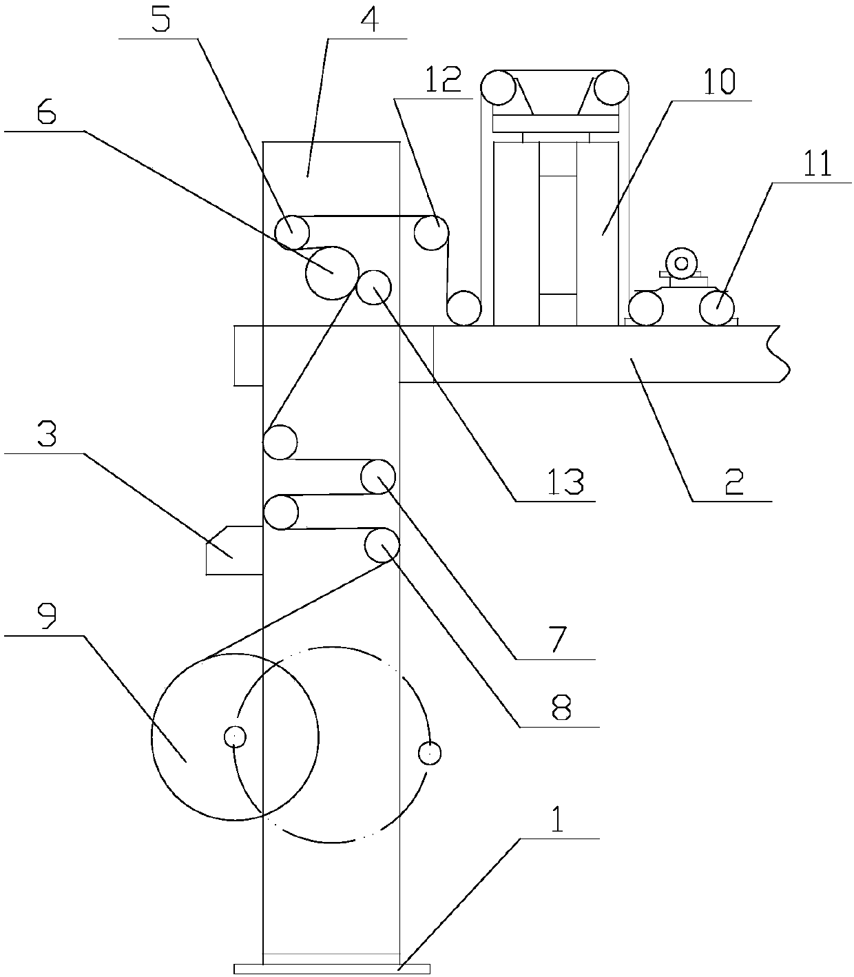
[0014] Such as figure 1 The shown built-in shaft rotary discharge device has a frame 1, the upper end of the frame 1 is provided with a support 2, the middle part is provided with a cutting device 3, and the top of the frame 1 is equipped with a traction upper wall panel 4;

[0015] A pendulum roller device 5 and a discharge traction device 6 are installed on the traction upper wallboard 4, a second pendulum roller device 7 and a guide roller 8 are arranged on the upper side of the frame 1, and a discharge roller 8 is provided at the middle position of the frame 1. Material device 9;

[0016] A deviation correcting device 10 is installed on the support 2, a tension sensing ro...


PUM

PropertyMeasurementUnit
Thicknessaaaaaaaaaa

Abstract

The invention relates to a shaft-built-in rotary charging device. The shaft-built-in rotary charging device is provided with a machine frame. A spacer is arranged at the upper end of the machine frame. A cutting device is arranged on the middle part of the machine frame. A pulling upper wallboard is mounted at the top end of the machine frame. A swing roll device and a charging pulling device aremounted on the pulling upper wallboard. A second swing roll device and a guiding roller are arranged above the machine frame. A charging device body is arranged in the middle of the machine frame. A deviation rectification device is mounted on the spacer. Tension sensing rollers are arranged on one side edge of the deviation rectification device. Tension wheel are arranged on the other side edge of the deviation rectification device. The shaft-built-in rotary charging device is simple in structure, convenient and rapid to use, good in charging effect, capable of improving the working efficiency and ensuring the effect that misoperation is not liable to occur high in working efficiency and capable of reducing the production cost.

Description

technical field [0001] The invention relates to a built-in shaft rotary discharging device. Background technique [0002] The existing rotary discharge device is prone to knotting and thread loosening during the discharge process, which requires staff to take care of it, which is time-consuming and laborious, reduces work efficiency, has poor discharge quality, and is prone to misoperation, which increases production costs. Contents of the invention [0003] The technical problem to be solved by the present invention is: to overcome the deficiencies in the prior art, to provide a built-in shaft rotary discharge device which is convenient and quick to use, has a good discharge effect, improves work efficiency, and is not prone to misoperation. [0004] The technical solution adopted by the present invention to solve the technical problem is: a built-in shaft rotary discharge device, which has a frame, the upper end of the frame is provided with a support, and the middle par...

Claims


Application Information

Patent Timeline
IPC IPC(8): B65H23/26B65H23/188B65H20/02B65H23/032B65H35/04
Inventor 侯鹏
Owner 侯鹏
Why Eureka
Eureka Blog
Learn More