Portal crane

A gantry crane and crane technology, applied in the direction of cranes, trolley cranes, traveling mechanisms, etc., can solve the problems of short sliding stroke of oil cylinders, frequent maintenance of wire ropes, short sliding distances, etc., and achieve high reliability and slippage. Lightweight and flexible, the effect of avoiding the trouble of maintenance

Pending Publication Date: 2018-01-19
SUZHOU DAFANG SPECIAL VEHICLE
View PDF5 Cites 4 Cited by
  • Summary
  • Abstract
  • Description
  • Claims
  • Application Information

AI Technical Summary

Problems solved by technology

The power for the slippage of the spreader is usually pulled by the hoisting wire rope, which has the disadvantages of complex structure and frequent maintenance of the wire rope; even if it is pushed and pulled by the oil cylinder, the oil cylinder is also arranged on the beam of the gantry crane. Above, due to the limitation of space, the length of the cylinder is limited so that the stroke of the cylinder is very short, resulting in a very short sliding distance
[0003] In addition, the gantry cranes (gantry cranes) currently on the market have both wheel-rail type and tire type, but according to the needs, they can not only use the module car as the chassis, but also can walk on the special guide rail according to the needs and realize it through the lifting of the oil cylinder. There is no lifting function

Method used


Image

  • Portal crane
  • Portal crane
  • Portal crane

Examples


Embodiment 1

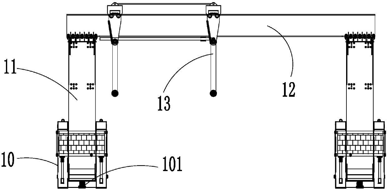
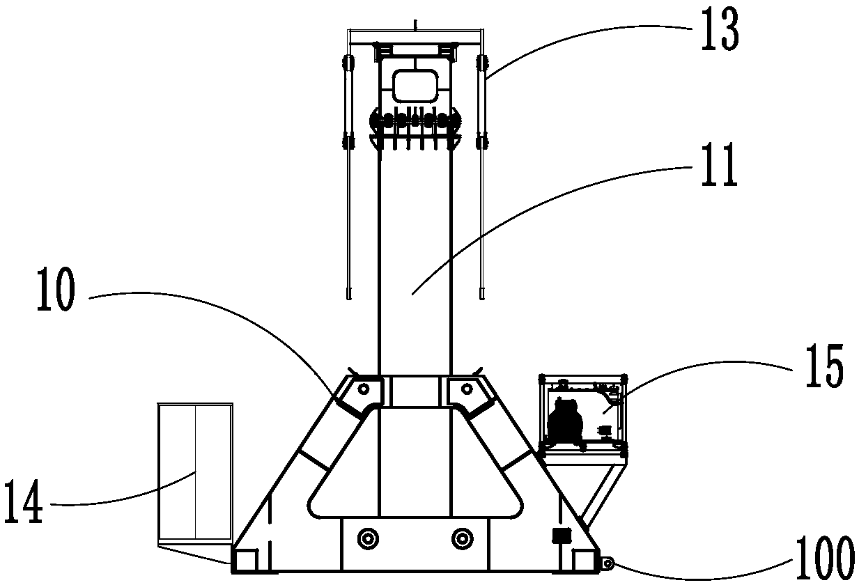
[0047] Such as Figure 5 , 6 Shown: in this embodiment: the moving mechanism includes the modular car 2, and the base 10 is fixed to the modular car 2 through the first connecting part 100.

[0048] The modular car 2 includes a frame, multiple suspension mechanisms and steering mechanisms arranged under the frame, and tires are connected below the suspension bracket. The suspension mechanism and the steering mechanism usually include a suspension cylinder and a steering cylinder. The modular car 2 is equipped with a special The hydraulic power station provides power for the suspension cylinder and the steering cylinder and drives them to travel. The modular car 2 and the lifting mechanism 11 can be respectively connected to a hydraulic power station or jointly connected to a hydraulic power station. Modular car 2 can be equipped with a remote control for walking, steering, and lifting. By operating the remote control, it can realize multiple actions of walking, steering, and lifti...

Embodiment 2

[0060] Such as Figure 7 , 8 Shown: In this embodiment: the moving mechanism includes a guide rail 30, a traveling cylinder 31, a guide bar is provided on the upper plane of the guide rail 30, and the guide groove at the bottom of the base 10 matches the guide bar, which can avoid the base 10 and its The deviation in the sliding process is prepared to ensure that the base 10 can advance in a predetermined direction under the push and pull of the traveling cylinder 31. The cylinder liner of the traveling cylinder 31 is connected to the guide rail 30, and the piston rod end of the traveling cylinder 31 is connected to the second connecting portion 101. Of course, the cylinder liner of the traveling cylinder 31 is connected to the second connecting portion 101, and the piston of the traveling cylinder 31 The rod end is connected to the guide rail.

[0061] When the crane body cooperates with the guide rail 30 for lifting and short-distance displacement, the following steps can be pe...


PUM


Abstract

The invention relates to a portal crane. The portal crane comprises a crane body and a moving mechanism arranged at the bottom of the crane body; the crane body comprises a pair of bases, lifting mechanisms arranged on the bases, a cross beam connected between the tops of the lifting mechanisms and a slidable lifting sling which is movably arranged on the cross beam; the slidable lifting sling comprises a drive lifting sling body, a driven lifting sling body connected with the drive lifting sling body and a power part used for driving the drive lifting sling body to slide; and the drive lifting sling body comprises fixing brackets, lifting plate assemblies connected to the fixing brackets and rolling assemblies connected to the bottoms of the fixing brackets, the rolling assemblies are arranged on the cross beam, and the power part is located under the cross beam. According to the portal crane, displacement and adjustment of the lifting sling on the cross beam are achieved, the slidingdistance is increased, sliding is more convenient and more flexible, and maintenance is not needed; and a modular car or a guide rail can be adopted as the moving mechanism, and therefore selection is flexible and diverse.

Description

Technical field [0001] The invention relates to a hoisting machine used in the fields of construction, power manufacturing, large-piece installation, transportation and the like, and in particular to a gantry crane. Background technique [0002] At present, the spreaders set on the gantry cranes on the market are usually fixed. When heavy objects need to be lifted: the gantry crane moves through the track, so that the spreader is aligned with the heavy object to complete the lifting, but because the track is relatively fixed, once the position of the heavy object cannot be passed Moving the alignment on the track will cause lifting difficulties. Therefore, mobile spreaders appeared on the market. In order to realize movement, similar spreaders on the existing market generally adopt static friction, that is, use low-friction materials to realize the movement of the spreader relative to the track. The power of the spreader slip is usually pulled by a hoisting wire rope. The use o...

Claims


Application Information

Patent Timeline
Patent Type & Authority Applications(China)
IPC IPC(8): B66C5/04B66C5/06B66C9/14B66C19/02
Inventor 刘继英于宁
Owner SUZHOU DAFANG SPECIAL VEHICLE
Why Eureka
Try Eureka