Check patentability & draft patents in minutes with Patsnap Eureka AI!

Rotating shaft lubricating structure of turbocharger

A turbocharger and lubricating structure technology, applied in the direction of machines/engines, engine components, mechanical equipment, etc., can solve the problems of short service life, fast wear, poor lubrication effect, etc., to reduce loss, smooth rotation of the shaft, reduce The effect of debris

Inactive Publication Date: 2018-01-19
崔敏娟
View PDF0 Cites 0 Cited by
  • Summary
  • Abstract
  • Description
  • Claims
  • Application Information

AI Technical Summary

Problems solved by technology

[0003] At present, only a shaft seal sleeve and a thrust bearing are installed between the rotating shaft and the intermediate housing of the existing turbocharger as a seal. In the specific application process, the lubrication between the shaft seal sleeve and the thrust bearing The effect is poor, the two wear out faster, and the service life is short

Method used


Image

  • Rotating shaft lubricating structure of turbocharger
  • Rotating shaft lubricating structure of turbocharger

Examples


Embodiment Construction

[0013] The technical solutions of the present invention will be further described below in conjunction with the accompanying drawings and through specific implementation methods.

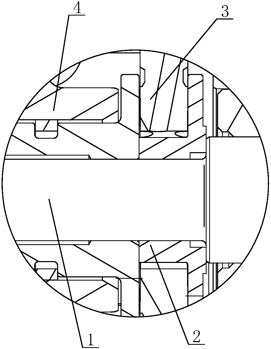
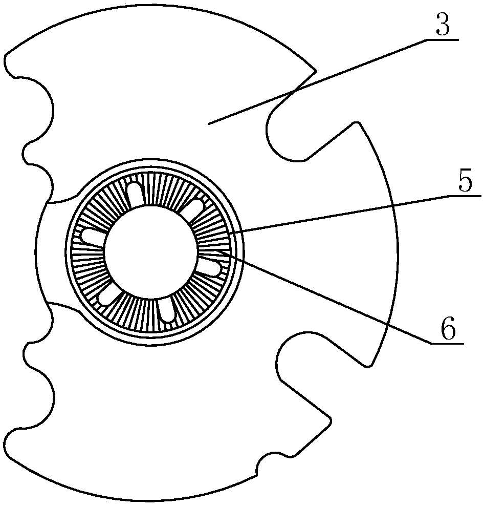
[0014] see figure 1 with figure 2 As shown, in this embodiment, a rotating shaft lubrication structure of a turbocharger includes a rotating shaft 1, a shaft seal sleeve 2 and a thrust bearing 3, and the rotating shaft 1 is arranged between the middle casing 4 of the turbocharger. Shaft seal fixed sleeve 2, the shaft seal fixed sleeve 2 is provided with a thrust bearing 3, an oil storage ring 5 is provided on the oil wedge surface of the thrust bearing 3, and several roads are arranged in the oil storage ring 5 The oil storage tank 6 , in this embodiment, the oil storage tank 6 has a straight-grained embossed structure, which is evenly distributed in the oil storage ring 5 in a radial shape.

[0015] The design of the oil storage tank 6 increases the amount of oil stored between the thrust bearin...


PUM


Abstract

The invention discloses a rotating shaft lubricating structure of a turbocharger. The rotating shaft lubricating structure comprises a rotating shaft, a shaft seal adapter sleeve and a thrust bearing;the shaft seal adapter sleeve is arranged between the rotating shaft and an intermediate shell of the turbocharger; and the thrust bearing is arranged on the shaft seal adapter sleeve, wherein an oilstorage ring is arranged on the oil wedge face of the thrust bearing and internally provided with a plurality of oil storage grooves. According to the rotating shaft lubricating structure of the turbocharger, an oil storage groove structure is additionally arranged in the range of the oil wedge face of the thrust bearing, so that the oil storage amount between the thrust bearing and the shaft seal adapter sleeve is increased, and accordingly, the rotating shaft rotates more smoothly, and heat generated by friction is reduced; and lubricating oil circulates more smoothly among parts, thus accumulation of sundries and impurities is reduced, and the loss of the thrust bearing and the shaft seal adapter sleeve is reduced.

Description

technical field [0001] The invention relates to a turbocharger, in particular to a lubricating structure for a rotating shaft of the turbocharger. Background technique [0002] A turbocharger is actually an air compressor that compresses air to increase intake air. It uses the inertial momentum of the exhaust gas discharged from the engine to drive the turbine in the turbine chamber, and the turbine drives the coaxial impeller, which presses the air sent by the air filter pipe to pressurize it into the cylinder. When the engine speed increases, the exhaust gas discharge speed and the turbine speed also increase synchronously, and the impeller compresses more air into the cylinder. The pressure and density of the air increase to burn more fuel. Increase the amount of fuel and adjust the engine speed accordingly. The output power of the engine can be increased. [0003] At present, only a shaft seal sleeve and a thrust bearing are installed between the rotating shaft and the...

Claims


Application Information

Patent Timeline
Patent Type & Authority Applications(China)
IPC IPC(8): F01D25/18
Inventor 崔敏娟
Owner 崔敏娟
Features
  • R&D
  • Intellectual Property
  • Life Sciences
  • Materials
  • Tech Scout
  • Unparalleled Data Quality
  • Higher Quality Content
  • 60% Fewer Hallucinations
Learn More