Multifunctional switching valve and water outlet device thereof

A multi-functional switching and switching valve technology, applied in the bathroom field, which can solve the problems of low service life, narrow application area, and inability to pass through identification and conduction.

Pending Publication Date: 2018-01-19
XIAMEN PSSIN TECH CO LTD
View PDF2 Cites 7 Cited by
  • Summary
  • Abstract
  • Description
  • Claims
  • Application Information

AI Technical Summary

Problems solved by technology

[0002] Applying the principle of automatic ballpoint pen switching to the bathroom field first appeared in the patent literature of CN101793331A, such as Picture 1-1 , Figure 1-2 As shown, it discloses the working method of switching the waterway through the button, but this kind of waterway switching is limited to the water inlet 4' and at least two water outlets 5' perpendicular to each other, that is, if the water inlet 4' is located at the bottom of the valve body, Then the two water outlets 5' are located in the radial position of the valve body. This waterway switching method has a narrow application area and can only be applied to shower or top spray products; at the same time, when the switching valve body is placed horizontally, push the button After 6' is pressed, because the button 6' has no self-weight limit, it is easy to form a virtual position, that is, the position of the button 6' after pressing may be consistent with the position of the button 6' in the pop-up state, and the stroke of the button 6' cannot be recognized at this time Position to determine which water inlet 4' is connected to which outlet 5'
[0003] In view of this, the industry has disclosed another button-type water outlet device, refer to the announcement number CN205036896U, such as Figure 2-1 , Figure 2-2 As shown, a radial water inlet 11a, a radially upper water outlet 12a, and a radially lower water outlet 13a are provided on the side wall of the water outlet body 1a, and the switching valve 2a is placed in the inner cavity of the water outlet body 1a. The pressing mechanism 5a drives the spool 3a to reciprocate along the axis of the switch valve 2a, so that one of the water inlet 11a can connect with the upper water outlet chamber 6a or the lower water outlet chamber 7a, thereby forming different switching waterways. The water inlet 11a and the upper and lower water outlets 12a, 13a are all located in the radial position of the switching valve 2a, which can facilitate the arrangement of the lifting rod and the hand-held shower on the water outlet device 1a, but this kind of scheme is in order to realize the valve core 3a It forms two closed waterways with the inner cavity of the switching valve 2a, so three sealing rings 32a need to be provided on the outer ring wall of the valve core 3a. The cavity wall generates friction, which causes the pressing mechanism 5a to generate greater frictional resistance when pressing; secondly, the sealing ring 32a will wear out during repeated friction, which will easily cause water leakage in the switching valve 2a, and the service life is low; at the same time The upper water outlet chamber 6a and the lower water outlet chamber 7a of this water outlet device are all arranged at the radial position of the switching valve 2a, so that when the valve core 3a switches the waterway, it is necessary to transfer the water in the upper water outlet chamber 6a or the lower water outlet chamber 7a. The waterway switch can only be realized after the squeeze is exhausted, so that the pressing mechanism 5a will produce a certain delay effect when pressing and switching
[0004] At the same time, the above two push-button switching valves cannot realize the function of flow switching or water temperature adjustment at the same time. If flow control or water temperature control is required, an additional flow control valve must be added to realize flow adjustment or temperature adjustment. , sometimes due to the limitation of the installation space, it is impossible to install, or considering the overall simple visual effect, both the flow regulating valve and the switching valve are installed on a water outlet device, and the overall layout is complicated

Method used


Image

  • Multifunctional switching valve and water outlet device thereof
  • Multifunctional switching valve and water outlet device thereof
  • Multifunctional switching valve and water outlet device thereof

Examples


no. 1 example

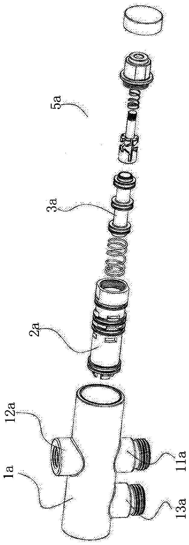
[0066] Such as Figure 3-1 —— Figure 3-6 As shown, a multifunctional switching valve includes an automatic ballpoint pen type pressing mechanism 1 , a sealing guide rod 2 , a valve core body 3 , a first spring 5 and a flow regulating device 6 .

[0067] The automatic ballpoint pen pressing mechanism 1 is consistent with the principle of the ordinary ballpoint pen pressing mechanism, but the specific connection and matching methods have certain characteristics. Specifically, the automatic ballpoint pen pressing mechanism 1 includes a static ratchet 11, a dynamic ratchet 12, and a ratchet seat. 13 and the second spring 14; the static ratchet 11 has an open end 111, and its bottom has a saw-toothed ratchet 112, and several positioning projections 113 are evenly distributed on the outer circumference of the ratchet 112; The movable ratchet 12 has an open end 121, and its bottom has a movable ratchet 122 that cooperates with the static ratchet ratchet 112, and the movable ratchet...

no. 2 example

[0084] Such as Figure 10 As shown, the upper structure of the switching valve 1000A including the pressing mechanism 1A, the sealing guide rod 2A, the valve core 3A, etc. is basically the same as that of the first embodiment of the switching valve, but the valve core seat 301A is additionally provided with Two mutually independent water inlets 37A, 37B, and at the same time, the peripheral portion of the ceramic stator 61A is provided with two water inlet through holes 611A, 611B, the aforementioned two water inlet through holes 611A, 611B are respectively connected to the valve core seat body 301A The two water inlets 37A, 37B are connected to each other; the peripheral portion of the ceramic moving piece 62A is provided with at least one flow regulating hole 621A and a sealing surface 622A, and the flow regulating hole 621A is rotatably connected to the two ceramic stationary pieces 62A. The water inlet holes 611A and 611B are interconnected, and at the same time, when the ...


PUM


Abstract

A multifunctional switching valve comprises an automatic ball pen type pressing mechanism, a sealing guide rod, a first spring and a valve element body. Through triggering of the automatic ball pen type pressing mechanism, the first spring can exert resilience opposite to pressing force to the sealing guide rod, the sealing guide rod constantly abuts against the pressing mechanism, the sealing guide rod reciprocates up and down in the axial position of the valve element body through the high-position and low-position stroke of the pressing mechanism, accordingly, a plug on the sealing guide rod can selectively block a first flow guiding hole or a second flow guiding hole, and opening / closing of a water inlet and a first water outlet or a second water outlet is finally achieved. meanwhile,through rotation of the included angle between the valve element body and a valve element base, the overflow area of a flow adjusting hole is changed, and accordingly the purposes of flow switchover and water temperature adjustment are achieved.

Description

technical field [0001] The invention relates to the field of sanitary ware, in particular to a multifunctional switching valve and a water outlet device equipped with the switching valve. Background technique [0002] Applying the principle of automatic ballpoint pen switching to the bathroom field first appeared in the patent literature of CN101793331A, such as Picture 1-1 , Figure 1-2 As shown, it discloses the working method of switching the waterway through the button, but this kind of waterway switching is limited to the water inlet 4' and at least two water outlets 5' perpendicular to each other, that is, if the water inlet 4' is located at the bottom of the valve body, Then the two water outlets 5' are located in the radial position of the valve body. This waterway switching method has a narrow application area and can only be applied to shower or top spray products; at the same time, when the switching valve body is placed horizontally, push the button After 6' ...

Claims


Application Information

Patent Timeline
Patent Type & Authority Applications(China)
IPC IPC(8): F16K11/044F16K1/52F16K3/08F16K31/44
CPCF16K11/044F16K31/44
Inventor 江烨
Owner XIAMEN PSSIN TECH CO LTD
Why Eureka
Try Eureka