Intelligent pressure reducing valve integrating power generation, data acquisition and automatic control functions as well as control method
A technology of data acquisition and pressure reducing valve, applied in the direction of functional valve type, engine components, valve details, etc., can solve the problems of troublesome maintenance, large amount of engineering, not involving detection modules, etc., to improve power generation efficiency, improve utilization rate, The effect of mitigating unstable power generation
- Summary
- Abstract
- Description
- Claims
- Application Information
AI Technical Summary
Problems solved by technology
Method used
Image
Examples
Embodiment 1
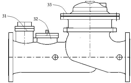
[0044] Such as figure 1 As shown, this embodiment provides an intelligent pressure reducing valve that integrates power generation, data collection, and control functions. This embodiment takes a T-shaped pressure reducing valve as an example. The intelligent decompression valve includes a decompression valve body 33, a power generation device 32, a data acquisition component, a data processing device and a display terminal.
[0045] The data acquisition components include flowmeters, pressure sensors, and water quality sensors; in the specific implementation process, other types of data acquisition components can also be used according to specific needs, such as collecting the opening of the valve body and the temperature of the fluid. In this embodiment, the flow meter adopts an ultrasonic flow meter 31 capable of measuring the consumption of the pipe network and having a temperature compensation function. The ultrasonic flow meter 31 is arranged at the front of the intelli...
Embodiment 2
[0064] Such as Figure 5 , Figure 6 , Figure 7 As shown, the difference between this embodiment and Embodiment 1 is that the intelligent decompression valve of this embodiment is a Y-type intelligent decompression valve; the power generation device 32 also includes a swing mechanism; perpendicular to the flow direction. At the inlet of the pressure reducing valve, there is a guide seat 13 for guiding the fluid. The flow passes through the conical guide surface, the cylindrical guide surface and the power generation assembly in sequence, and the diameter of the cylindrical guide surface matches the size of the runner.
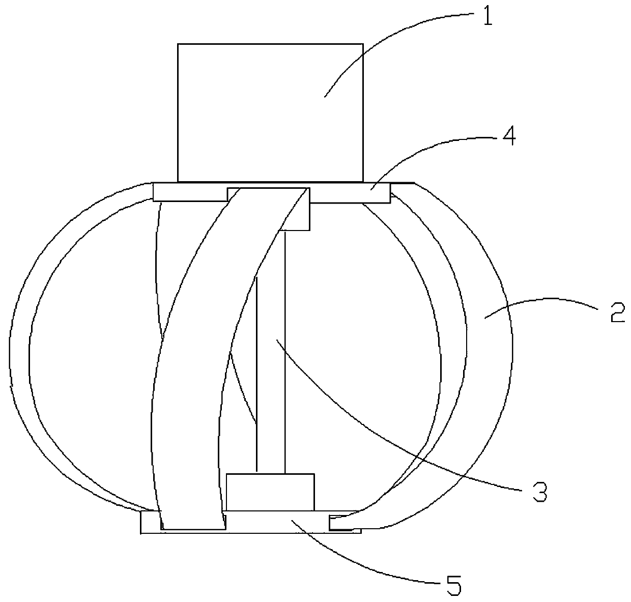
[0065] Such as Figure 7 As shown, the power generation assembly 9 is placed inside the pipeline, and also includes a swing mechanism that can support the vertical swing of the power generation assembly 9 relative to the axial direction of the fixed shaft 11; the fixed shaft 11 is fixed on a support seat, and in this embodiment The valve housing is fixedl...
Embodiment 3
[0072] Such as Figure 8 As shown, the difference between this embodiment and Embodiment 1 or Embodiment 2 is that a small runner 8 is provided inside the runner 2; the structure of the small runner 8 is consistent with that of the runner 2; The positions of the two blades of the wheel are staggered. The material of the small runner can be selected from light materials, so as to reduce the weight of the power generation components.
[0073]When the fluid flow rate is constant and the flow rate is normal, the small runner and the big runner rotate under the impact of the fluid, thereby driving the rotating shaft 3 to rotate. Compared with the rotation of the main shaft 3 in Embodiment 1 and Embodiment 2, Embodiment 2 increases The small runner increases the contact surface with the fluid so as to increase the thrust of the fluid on the blades and increase the rotation speed of the main shaft 3 . When the fluid flow rate decreases and the flow velocity decreases, the small run...
PUM
 Abstract
Description
Claims
Application Information
 - R&D
- Intellectual Property
- Life Sciences
- Materials
- Tech Scout
- Unparalleled Data Quality
- Higher Quality Content
- 60% Fewer Hallucinations
Browse by: Latest US Patents, China's latest patents, Technical Efficacy Thesaurus, Application Domain, Technology Topic, Popular Technical Reports.
© 2025 PatSnap. All rights reserved.Legal|Privacy policy|Modern Slavery Act Transparency Statement|Sitemap|About US| Contact US: help@patsnap.com


