Eureka AIR delivers breakthrough ideas for toughest innovation challenges, trusted by R&D personnel around the world.

Guide rail device used for antenna test of microwave dark room

A technology of guide rail device and microwave anechoic chamber, which is applied in the direction of antenna radiation pattern, etc., can solve the problems of heavy workload and labor-intensive laying of absorbing materials, and achieve the effect of improving test efficiency and liberating labor

Active Publication Date: 2018-01-19
THE 41ST INST OF CHINA ELECTRONICS TECH GRP
View PDF5 Cites 5 Cited by
  • Summary
  • Abstract
  • Description
  • Claims
  • Application Information

AI Technical Summary

Problems solved by technology

[0004] Aiming at the problem that the laying of absorbing materials requires a lot of work and a lot of manpower when testing the existing microwave anechoic chamber antenna, the present invention provides a guide rail device for microwave anechoic chamber antenna testing

Method used


Image

  • Guide rail device used for antenna test of microwave dark room

Examples


Embodiment Construction

[0013] The specific embodiment of the present invention will be further described below in conjunction with accompanying drawing and specific embodiment:

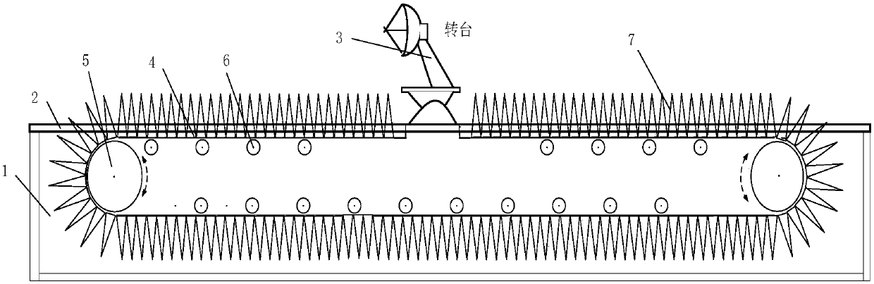
[0014] combine figure 1 , a guide rail device for antenna testing in a microwave anechoic chamber, including a guide rail, the guide rail is composed of two track pieces arranged side by side, the gap between the two track pieces is used as a guide rail groove 1, and a conveyor belt structure is arranged in the guide rail groove, two The upper part of the track member is a track chute 2, on which a turntable 3 is slidably connected.

[0015] When placing the guide rail, a groove suitable for the length and width of the guide rail can be excavated in the foundation so that the guide rail can be erected flush with the ground without affecting the space of the guide rail groove.

[0016] The conveyor belt structure includes a conveyor belt 4 and a conveyor belt bracket. Two transmission wheel shafts 5 and a plurality of suppo...


PUM


Abstract

The invention provides a guide rail device used for an antenna test of a microwave dark room. The device comprises a guide rail which comprises two parallelly arranged track pieces. The gap between the track pieces is used as guide rail groove. A conveyer belt structure is arranged in the guide rail groove. The upper parts of the track pieces serve as track slide grooves which are slidably connected with a rotary bench. Two transmission wheel shafts and multiple support wheel shafts are arranged on a conveyer belt support. The support wheel shafts are uniformly arranged on the conveyer belt support. The transmission wheel shafts are arranged on the front side and the back side of the conveyer belt support. A conveyer belt is laid on the conveyer belt support and is supported by the supportwheel shafts and driven to carry out transmission through the transmission wheel shafts. The both ends of the conveyer belt are connected to the front end and the back end of the lower side of the rotary bench. The conveyer belt is capable of rotating along with the rotary bench. According to the invention, the whole process is free of manual intervene; work of re-moving and re-laying in positionadjustment of the rotary bench in each test are omitted; workers are relieved; and test efficiency is improved.

Description

technical field [0001] The invention relates to the field of microwave anechoic chamber antenna testing, in particular to a guide rail device for microwave anechoic chamber antenna testing. Background technique [0002] In the antenna measurement in the microwave anechoic chamber, there is a need to change the test distance. Changes in different test distances can change the dynamic range of the system and the electromagnetic environment of the location. It is often necessary to install the test turntable on the guide rail to meet the requirement that different test distances can be adjusted. Due to the heavy weight of the turntable and the long length of the guide rail, the guide rails are generally made of metal materials, and a metal cover is laid on the guide rail surface, and the metal guide rail and the cover surface will seriously affect the electromagnetic environment of the darkroom, and it is necessary to lay suitable absorbing material to reduce its impact. [...

Claims


Application Information

Patent Timeline
Patent Type & Authority Applications(China)
IPC IPC(8): G01R29/10
Inventor 周杨杜刘革赵锐金曦宸
Owner THE 41ST INST OF CHINA ELECTRONICS TECH GRP
Why Eureka
Eureka Blog
Learn More