Optical module

A technology of optical modules and optical devices, which is applied in the field of optical communications, can solve the problems of complex assembly work, large overall size, unfavorable miniaturization design of optical modules, etc., to achieve the advantages of easy assembly and replacement, reduced assembly workload, and guaranteed working performance Effect

Active Publication Date: 2018-01-19
HISENSE BROADBAND MULTIMEDIA TECH
View PDF4 Cites 10 Cited by
  • Summary
  • Abstract
  • Description
  • Claims
  • Application Information

AI Technical Summary

Problems solved by technology

In the existing multi-channel parallel optical modules, multiple sets of transmitting and receiving optical devices used to transmit signals are usually arranged in a matrix, and the optical fiber heads corresponding to the transmitting and receiving optical devices are fixed by dispensing. On the base of the optical module, the assembly work is more complicated. Once the optical fiber hea

Method used


Image

  • Optical module
  • Optical module
  • Optical module

Examples


Embodiment Construction

[0024] The following will clearly and completely describe the technical solutions in the embodiments of the present invention with reference to the accompanying drawings in the embodiments of the present invention. Obviously, the described embodiments are only some, not all, embodiments of the present invention. Based on the embodiments of the present invention, all other embodiments obtained by persons of ordinary skill in the art without making creative efforts belong to the protection scope of the present invention.

[0025] In the description of the present invention, it should be understood that the orientation or positional relationship indicated by the terms "upper", "lower", "vertical", "horizontal", "inner", "outer" etc. The method or positional relationship is only for the convenience of describing the present invention and simplifying the description, but does not indicate or imply that the referred device or element must have a specific orientation, be constructed a...


PUM


Abstract

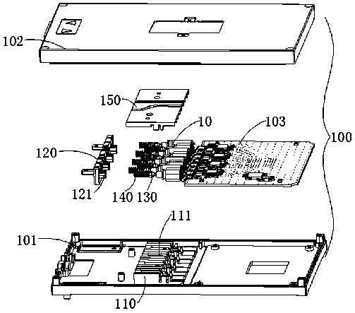
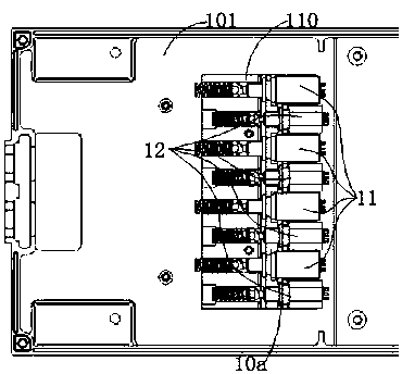
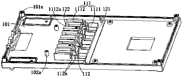
The invention application provides an optical module comprising an upper housing and a lower housing mutually buckled; multipath optical devices are electrically connected with a circuit board on thelower housing so as to transmit photoelectric signals; the optical module also comprises a pedestal arranged on the lower housing and a side plate connected on one side of the pedestal; a plurality ofgrooves are arranged in the pedestal; optical devices connected with optical fiber heads are clamped in the grooves; the optical fiber heads and springs sleeved on the optical fiber head end portionsare supported by the grooves; poles arranged on the side plate insert into the grooves and abut against the springs; a cover plate covering the optical devices is detachably connected with the pedestal. The springs can support the optical fiber heads and adjust the fitting allowance of the optical fiber heads in the grooves, thus preventing the optical fiber heads from having offsets in the pedestal, and effectively ensuring the working performance of connected optical devices and fibers; the optical devices and optical fiber heads of the optical module are convenient to assemble, thus effectively reducing the optical module assembling workload.

Description

technical field [0001] The invention relates to the technical field of optical communication, in particular to an optical module. Background technique [0002] An optical network refers to a network structure that uses optical fiber transmission, and an optical module is a core device that transmits optical signals through optical fibers and completes photoelectric conversion in the optical network. With the continuous development of optical communication technology, the amount of information and data transmitted on the optical network is gradually increasing, and the optical module based on the form of a single optical device cannot meet the user's requirements for transmission rate and transmission capacity due to the limited transmission bandwidth. . In order to meet the user's demand for high bandwidth and improve the transmission rate and capacity of the optical module, a multi-channel parallel optical module packaged with multiple optical devices emerged as the times ...

Claims


Application Information

Patent Timeline
IPC IPC(8): G02B6/42
Inventor 陈金磊刘寅龙吴铁山樊凤梅司宝峰
Owner HISENSE BROADBAND MULTIMEDIA TECH
Why Eureka
Try Eureka