
Detection method of array substrate drive circuit

A technology for driving circuits and array substrates, used in instruments, static indicators, etc., can solve problems such as reducing the yield of OLED products, short circuits or open circuits, and increasing the cost of back-end finished products.

Active Publication Date: 2018-01-19
HEFEI XINSHENG OPTOELECTRONICS TECH CO LTD +1
View PDF6 Cites 10 Cited by
  • Summary
  • Abstract
  • Description
  • Claims
  • Application Information

AI Technical Summary

Problems solved by technology

The wiring of the pixel driving circuit inside the OLED panel is very complicated, and there are many types of bad wiring
For example, the circuit of these pixel driving circuits may be short-circuited or disconnected (or called open circuit), which will cause the pixel driving circuit to be abnormal.
This will cause problems such as reducing the yield rate of OLED products and increasing the cost of back-end finished products.

Method used


Image

  • Detection method of array substrate drive circuit
  • Detection method of array substrate drive circuit
  • Detection method of array substrate drive circuit

Examples


Embodiment Construction

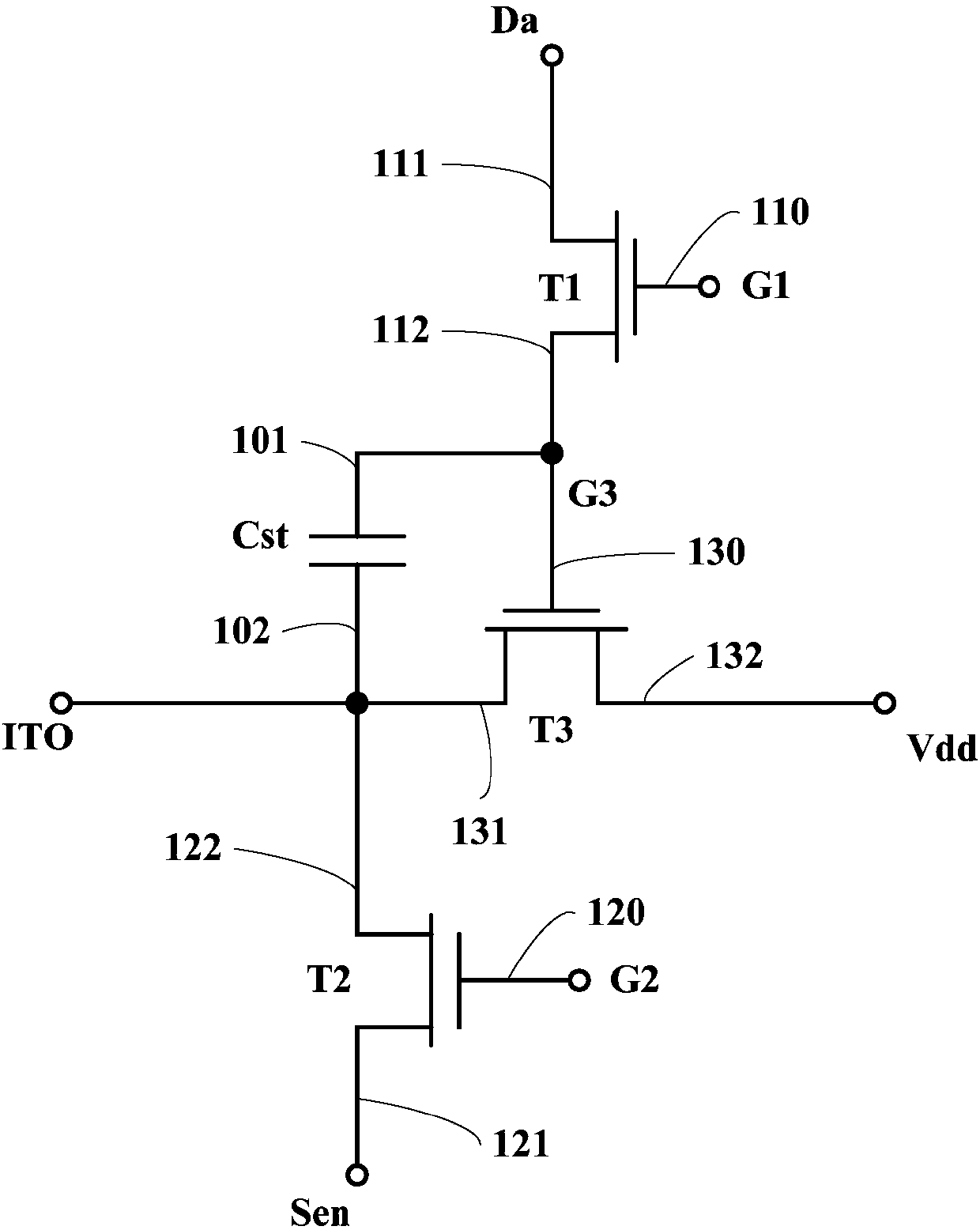
[0026] Various exemplary embodiments of the present disclosure will now be described in detail with reference to the accompanying drawings. The description of the exemplary embodiments is merely illustrative and in no way limits the disclosure, its application or uses in any way. The present disclosure may be implemented in many different forms and is not limited to the embodiments described herein. These embodiments are provided so that this disclosure will be thorough and complete, and will fully convey the scope of the disclosure to those skilled in the art. It should be noted that unless specifically stated otherwise, the relative arrangements of parts and steps, compositions of materials, numerical expressions and numerical values ​​set forth in these embodiments are to be interpreted as illustrative only and not as limiting.

[0027] As used in this disclosure, "first," "second," and similar words do not denote any order, quantity, or importance, but are merely used to ...


PUM


Abstract

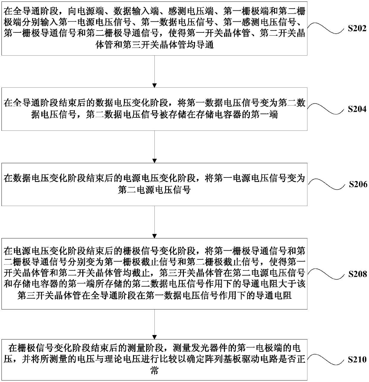
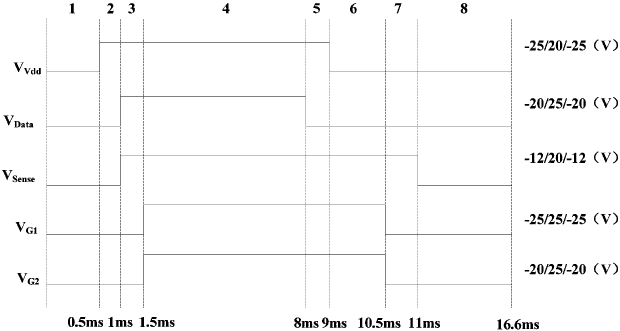
The invention provides a detection method of an array substrate drive circuit. The method includes: in a fully conducting stage, inputting a first power supply voltage signal to a power supply end, inputting a first data voltage signal to a data input end, inputting a first sensing voltage signal to a first sensing voltage end, inputting a first grid conducting signal to a first grid end, and inputting a second grid conducting signal to a second grid end; in a data voltage change stage, changing the first data voltage signal into a second data voltage signal; in a power supply voltage change stage, changing the first power supply voltage signal into a second power supply voltage signal; in a grid signal change stage, changing the first grid conducting signal and the second grid conductingsignal into a first grid blocking signal and a second grid blocking signal; in a measuring stage, measuring the voltage of the first electrode end of a light-emitting device, and comparing the measured voltage with theoretical voltage to determine whether the array substrate drive circuit is normal or not. By the method, the array substrate drive circuit can be detected.

Description

technical field [0001] The present disclosure relates to the field of display technology, and in particular, to a detection method of a driving circuit of an array substrate. Background technique [0002] In the display industry, OLED (Organic Light Emitting Diode, Organic Light Emitting Diode) has advantages such as high contrast ratio and high color gamut, and is the mainstream trend in the development of display panels in the future. In particular, AMOLED (Active Matrix Organic Light Emitting Diode) has the advantages of wide viewing angle and fast response speed. However, OLED products have stricter requirements on TFT (Thin Film Transistor, thin film transistor) backplanes. The circuit of the pixel drive circuit inside the OLED panel is very complex, and there are many types of defective circuits. For example, the lines of these pixel driving circuits may be short-circuited or open-circuited (or referred to as open circuits), resulting in abnormal pixel driving circui...

Claims


Application Information

Patent Timeline
Patent Type & Authority Applications(China)
IPC IPC(8): G09G3/00
CPCG09G3/006G09G3/3208G09G2330/12G09G3/3291
Inventor 袁志东李永谦
Owner HEFEI XINSHENG OPTOELECTRONICS TECH CO LTD
Learn More