
Converter control method

A control method and converter technology, applied in the direction of converting AC power input to DC power output, conversion equipment that can be converted to DC without intermediate conversion, power transmission AC network, etc., can solve the problem of converter transformer network side bushing Problems such as CT saturation out of control, to achieve high economy and avoid out of control

Active Publication Date: 2018-01-19
NR ELECTRIC CO LTD +1
View PDF10 Cites 1 Cited by
  • Summary
  • Abstract
  • Description
  • Claims
  • Application Information

AI Technical Summary

Problems solved by technology

In order to solve this problem, the present invention proposes an economical control method to avoid the out-of-control problem caused by CT saturation of the bushing on the grid side of the converter transformer

Method used


Image

  • Converter control method
  • Converter control method
  • Converter control method

Examples


Embodiment Construction

[0020] The technical solutions of the present invention will be described in detail below in conjunction with the accompanying drawings and specific embodiments.

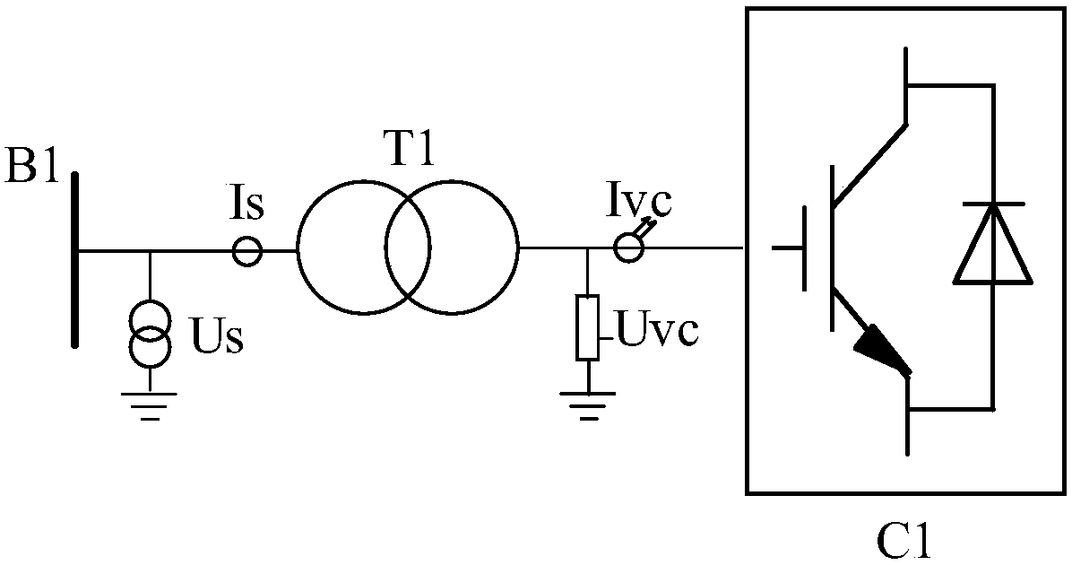
[0021] attached figure 1 Schematic diagram of measuring point configuration for the flexible DC system. The AC side of the voltage source converter C1 is connected to the bus B1 of the AC system through the converter transformer T1. The grid side of the converter transformer T1 is equipped with an electromagnetic voltage transformer Us and an electromagnetic current transformer Is. The converter transformer T1 The valve side is equipped with electronic voltage transformer Uvc and electronic current transformer Ivc. Generally, the active and reactive power of the grid side of the converter transformer is controlled as the set value, so the measurement values ​​of voltage transformer Us and current transformer Is are mainly used. , but the dynamic range of the control current transformer Is is generally only 2 times,...


PUM


Abstract

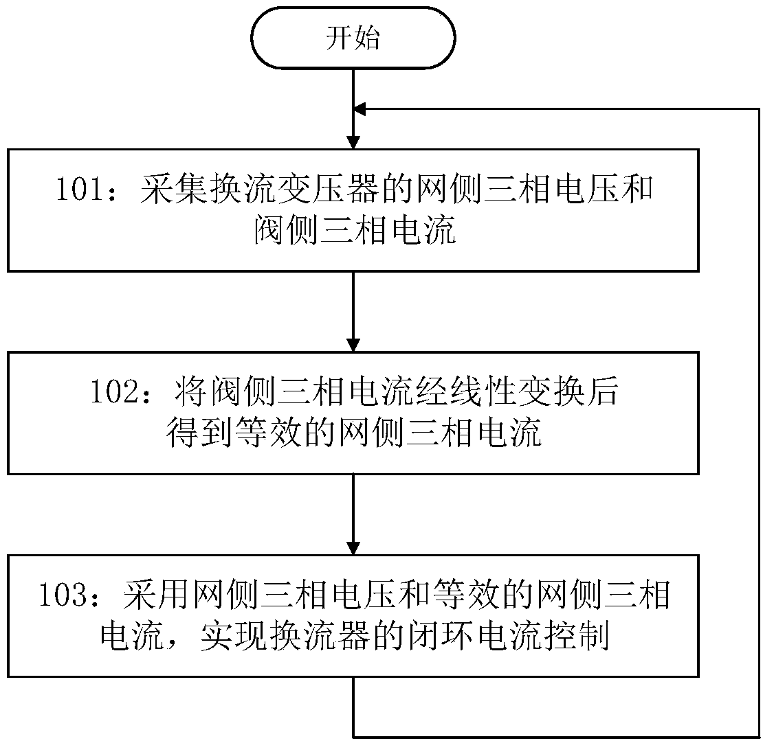
The invention discloses a converter control method applied to a voltage source type converter. The alternating current side of the voltage source type converter is connected with an alternating current system through a converter transformer; and closed loop current control of the converter is realized by collecting a grid-side voltage and a valve-side current. By adoption of the control method provided by the invention, the problems of grid-side sleeve CT saturation of the converter transformer and caused out of control can be avoided, without needing to add new measurement equipment, therebyachieving relatively high economic efficiency.

Description

technical field [0001] The invention belongs to the technical field of power electronics, and in particular relates to a method for controlling a converter. Background technique [0002] Flexible DC transmission uses voltage source converters, which can independently and quickly control active power and reactive power, thereby improving system stability, suppressing system frequency and voltage fluctuations, and improving the steady-state performance of grid-connected AC systems. With the depletion of fossil energy and the increasing pressure to improve the environment, China and the world are facing a strategic adjustment of energy structure, large-scale development and utilization of new energy is imperative. [0003] The AC side of the converter of the flexible DC transmission system is connected to the AC system through the converter transformer. Generally, the active and reactive power of the grid side of the converter transformer is controlled as the set value. When a...

Claims


Application Information

Patent Timeline
Patent Type & Authority Applications(China)
IPC IPC(8): H02J3/36H02M7/00
CPCH02M5/12H02M7/797H02J3/36H02M1/0003
Inventor 卢宇汪楠楠董云龙田杰李海英姜崇学王佳成丁久东胡兆庆鲁江
Owner NR ELECTRIC CO LTD
Learn More