
Cylindrical magnetic bracket-type permanent magnet governor

A permanent magnet governor, cylindrical technology, applied in the field of cylindrical magnetic support type permanent magnet governor, can solve the problems of small adjustment range, large volume, governor design error, etc., to achieve a large speed regulation range, The effect of small size and simple structure

Active Publication Date: 2018-01-19
ANHUI WOLF POWER TECH
View PDF4 Cites 6 Cited by
  • Summary
  • Abstract
  • Description
  • Claims
  • Application Information

AI Technical Summary

Problems solved by technology

[0005] The existing barrel-type permanent magnet governor has a complex structure, large volume, and a small adjustment range. The load cannot be completely disengaged at the maximum air gap, and the push-pull mechanism requires a large pulling force to realize the air gap change, which has a large amount of axial movement. The system cannot be applied, and even the design error of some governors makes the permanent magnet rotor collide with the conductor rotor, causing fatal damage

Method used


Image

  • Cylindrical magnetic bracket-type permanent magnet governor
  • Cylindrical magnetic bracket-type permanent magnet governor
  • Cylindrical magnetic bracket-type permanent magnet governor

Examples


Embodiment Construction

[0028] The technical solutions in the embodiments of the present invention will be clearly and completely described below in conjunction with the accompanying drawings in the embodiments of the present invention. Obviously, the described embodiments are only a part of the embodiments of the present invention, rather than all the embodiments. Based on the embodiments of the present invention, all other embodiments obtained by those of ordinary skill in the art without creative work shall fall within the protection scope of the present invention.

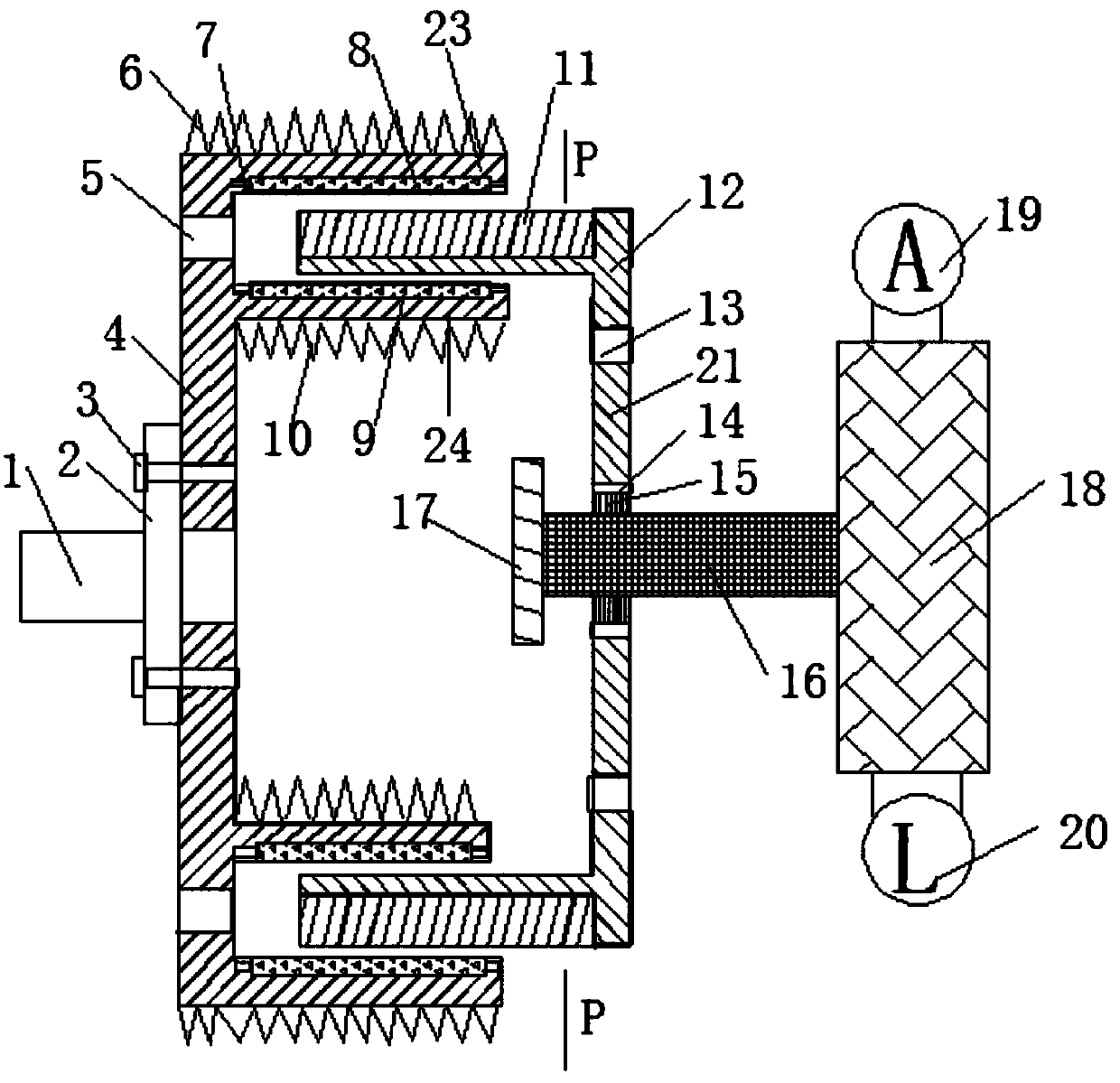
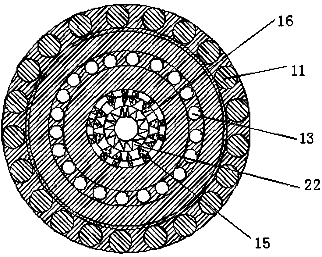
[0029] See Figure 1-Figure 3 As shown, the present invention is a cylindrical magnetic holder type permanent magnet governor, including a cylindrical conductor rotor 4, a cylindrical permanent magnet rotor 21 and a speed regulating device 18; the cylindrical conductor rotor 4 and the flange 2 are passed through bolts 3 The flange 2 is connected to the driving shaft 1. The cylindrical conductor rotor 4 is provided with a first vent 5 at ...


PUM


Abstract

The invention discloses a cylindrical magnetic bracket-type permanent magnet governor, which comprises a cylindrical conductor rotor, a cylindrical permanent magnet rotor and a speed regulating device, wherein the cylindrical conductor rotor comprises an outer cylinder and an inner cylinder; the inner wall of the outer cylinder is connected with an outer conductor cylinder; the outer wall of the inner cylinder is connected with an inner conductor cylinder; the cylindrical permanent magnet rotor is provided with a magnetic bracket; a circle of magnetic holes are uniformly distributed in the outer wall of the magnetic bracket; a permanent magnet is arranged in each magnetic hole; an electromagnetic valve is arranged on a base of the cylindrical permanent magnet rotor; the base of the cylindrical permanent magnet rotor is hinged with the electromagnetic valve; the cylindrical permanent magnet rotor is connected with a driven shaft; the speed regulating device is connected with one end ofthe driven shaft and the other end of the driven shaft is connected with a baffle plate; and the cylindrical permanent magnet rotor slides between the baffle plate and the speed regulating device andis prevented from colliding with the conductor rotor, and the speed regulating range can be 0-98%, so that motor can be completely separated from load. The speed regulating device is connected with the electromagnetic valve through wireless communication, so that the driving force is not needed while non-contact transmission of power is achieved.

Description

Technical field [0001] The invention relates to a wireless speed regulating device, in particular to a cylindrical magnetic support type permanent magnet speed regulator. Background technique [0002] Permanent magnet speed regulation (permanent magnet transmission) is a revolution in the history of transmission. Its simple structure, reliable operation, energy saving and consumption reduction characteristics are well used in modern industries. It is mainly used in petroleum, petrochemical, electric power, mining, Energy-saving motor drive systems in steel, chemical, cement and other industries. [0003] The basic principle of the disc type permanent magnet governor is the same as that of the barrel type permanent magnet governor. Both the conductor rotor and the permanent magnet rotor produce relative movement, thereby generating an alternating induced magnetic field on the conductor rotor. It meshes with the alternating permanent magnetic field to generate torque and transfer po...

Claims


Application Information

Patent Timeline
Patent Type & Authority Applications(China)
IPC IPC(8): H02K49/04H02K49/10
Inventor 徐修昆
Owner ANHUI WOLF POWER TECH
Learn More