Rubber injection molding and vulcanization production line

A rubber injection and production line technology, applied in coating and other directions, can solve the problems of occupying more space, affecting production efficiency, and obvious operation delay, so as to reduce labor costs, improve production efficiency, and reduce operation delay.

Pending Publication Date: 2018-01-23
湖南众钧科技有限公司
View PDF6 Cites 23 Cited by
  • Summary
  • Abstract
  • Description
  • Claims
  • Application Information

AI Technical Summary

Problems solved by technology

Although this device can improve production efficiency and reduce labor intensity to a certain extent, it still needs further improvement in many aspects.
[0004] The plasticizing device of the rubber molding machine of this device is set on the side close to the rubber vulcanizing machine. The plasticizing device, the mold opening mechanism, the product taking mechanism, and the product output belt are respectively located on both sides of the rubber molding machine, and the mold opening mechanism, The product taking mechanism and the product output belt are set along the length direction of the conveying track. In this way, one operator is required at the plasticizing device and one operator at the product output belt during production, that is to say, at least two operators are required on a production line. operators; the mold opening mechanism, product taking mechanism and product output belt are set along the length of the conveyor track, which takes up a lot of space; multiple rubber vulcanizers are arranged in a single row on the same side of the conveyor track, which also takes up a lot of space. In addition, the mold-moving mechanism of this device is set on the rubber molding machine and the rubber vulcanizing machine, and the operation delay is obvious, which affects the production efficiency

Method used


Image

  • Rubber injection molding and vulcanization production line
  • Rubber injection molding and vulcanization production line
  • Rubber injection molding and vulcanization production line

Examples


Embodiment

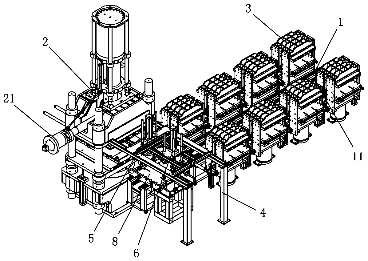
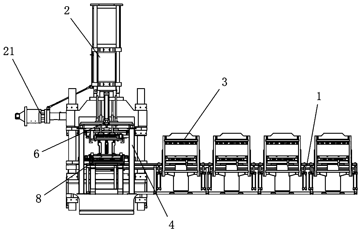
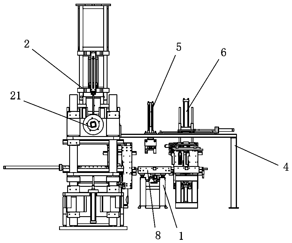
[0046] Such as Figure 1 to Figure 4 As shown, a rubber injection molding vulcanization production line of the present invention includes a conveying guide rail 1, a rubber injection molding machine 2 is installed in the front section of the conveying guide rail 1, and a flat vulcanizing machine 3 is installed in the rear section of the conveying guide rail 1. At the front of the rubber injection molding machine 2, a supporting platform 4 straddling above the conveying guide rail 1 is installed. One end of this supporting platform 4 is connected with the upper seat of the rubber injection molding machine 2, and the front portion of the rubber injection molding machine 2 on the supporting platform 4 is equipped with a mold opening mechanism 5 and a product-taking mechanism 6 . The mold opening mechanism 5 and the product taking mechanism 6 are arranged along a direction perpendicular to the conveying guide rail 1 . A linear guide rail 7 is provided on the conveying guide rail ...


PUM


Abstract

The invention discloses a rubber injection molding and vulcanization production line comprising a conveying guide rail. A rubber injection molding machine is installed on the front section of the conveying guide rail. Vulcanizing presses are installed on the back section of the conveying guide rail. A supporting platform stretching across the conveying guide rail is installed on the front portionof the rubber injection molding machine. One end of the supporting platform is connected with an upper base of the rubber injection molding machine. A mold opening mechanism and a product fetching mechanism are installed on the supporting platform and located on the front portion of the rubber injection molding machine. The mold opening mechanism and the product fetching mechanism are arranged inthe direction perpendicular to the conveying guide rail. A linear guide rail is arranged on the conveying guide rail. The linear guide rail is provided with a conveying trolley in a sliding manner, and the conveying trolley is used for taking out a mold from the rubber injection molding machine, conveying the mold to the vulcanizing presses and conveying vulcanized products to the position below the product fetching mechanism. The rubber injection molding and vulcanization production line is small in occupied floor space, needs a small number of personnel and has high production efficiency.

Description

technical field [0001] The invention belongs to the technical field of rubber molding, and in particular relates to a rubber injection molding vulcanization production line. Background technique [0002] Traditional rubber molding and vulcanizing production lines usually include independent rubber molding machines and rubber vulcanizing machines. The basic process of rubber injection molding is feeding, plasticizing, clamping, injection, pressure-holding vulcanization, demoulding and taking products, which can be automated on the rubber molding machine. The basic process of rubber vulcanization is manual feeding, clamping, pressure vulcanization, etc., and its degree of automation is low. Traditional flat vulcanizing machines are all single-machine operation, each vulcanizing machine must be equipped with a worker, the production efficiency is low, the labor intensity is high, and the quality consistency of the produced products is not strong. [0003] In order to solve th...

Claims


Application Information

Patent Timeline
Patent Type & Authority Applications(China)
IPC IPC(8): B29C45/00B29C45/17B29C35/00
Inventor 肖才贵李志强董鸣丁利
Owner 湖南众钧科技有限公司
Why Eureka
Try Eureka