Wind turbine generator blade bonding corner and preparation method thereof

A technology for wind turbines and bonding angles, which is applied in wind power generation, mechanical equipment, wind engines, etc., to achieve the effects of overcoming wrinkling deformation, high bonding quality, and solving the cracking of blade adhesives

Pending Publication Date: 2018-01-23
GUODIAN UNITED POWER TECH
View PDF0 Cites 7 Cited by
  • Summary
  • Abstract
  • Description
  • Claims
  • Application Information

AI Technical Summary

Problems solved by technology

[0005] The technical problem to be solved by the present invention is to provide a wind turbine blade bonding angle, which can

Method used


Image

  • Wind turbine generator blade bonding corner and preparation method thereof
  • Wind turbine generator blade bonding corner and preparation method thereof

Examples


Embodiment 1

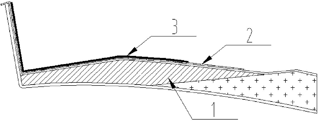
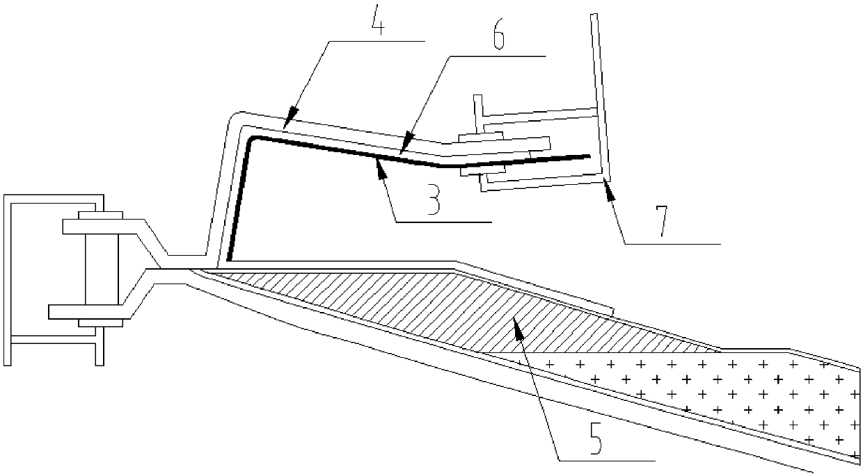
[0038] Refer to attached figure 1 and 2 As shown, this embodiment is used to prepare the SS surface rear edge bonding angle with the PS surface rear edge liner, and its specific preparation method includes the following steps:

[0039] (1) After pre-curing the PS surface shell 1 of the blade PS surface shell of the PS surface trailing edge liner, remove the auxiliary materials within the range of 200mm from the parting line L3m to L15m of the PS surface shell 1 trailing edge of the blade, and clean it up. According to the PS surface shell 1 Lay the vacuum bag film close to the inner wall 2, lay a layer of 150mm wide triaxial cloth within the parting line, then pour the mixed resin evenly on the triaxial cloth, use rollers to soak the resin into the fiber cloth, and drive out Bubble and make the fiber cloth conform to the inner wall of the shell in this area, repeat the above action, and then lay two layers of biaxial cloth and resin, and make the rear edge liner 3 of the PS s...

Embodiment 2

[0047] This embodiment is used to prepare the rear edge bonding angle of the PS surface with the SS surface rear edge liner, and its specific preparation method includes the following steps:

[0048] (1) Production of SS surface trailing edge lining board After the shell layer of the blade SS surface is laid, enter the auxiliary material layout stage, after laying the release cloth, lay 3 layers within the parting line L8m~L14m of the trailing edge of the blade SS surface shell The 180mm wide biaxial cloth is then poured together with the shell of the blade SS surface to obtain the SS surface trailing edge liner.

[0049] (2) After the resin is pre-cured, open the vacuum bag film, use a wallpaper knife to cut off the 30mm release cloth around the rear edge lining board of the SS surface, and open it from one corner, tear the release cloth to remove the rear edge lining board of the SS surface Separate from the SS surface shell, remove the release cloth on the liner, and cut th...


PUM


Abstract

The invention discloses a wind turbine generator blade bonding corner and further discloses a preparation method of the wind turbine generator blade bonding corner. The wind turbine generator blade bonding corner is provided with lining plates and a U-shaped structure. The outer side shape of the U-shaped structure is matched with the inner side shape of a corresponding blade bonding area, and thelining plates are arranged along the inner side of one edge or two adjacent edges of the U-shaped structure. The preparation method comprises the steps that (1) the lining plates are prepared insidethe parting line of one face of a blade shell according to the shell inner wall shape, and the lining plates are subjected to demolding and edge trimming; and (2) a bonding corner laying layer is manufactured through a fiber cloth and resin, then the parting line side of the prepared lining plates is aligned at the center line of the bonding corner laying layer to place the bonding corner laying layer and the lining plates between a bonding corner mold and the blade shell, the lining plates are clamped on the bonding corner mold through a clamp, after the bonding corner laying layer is solidified, demolding is conducted, and then the bonding corner with the lining plates is obtained. The following property of the bonding corner with the lining plates and the shell is high, the defects thatan existing bonding corner is corrugated and deformed, and positioning is poor can be overcome, and the blade bonding quality is improved.

Description

technical field [0001] The invention relates to the technical field of wind power blade preparation, in particular to a wind power unit blade bonding angle and a preparation method thereof. Background technique [0002] The blades of wind turbines are usually divided into pressure surface (PS surface) and suction surface (SS surface). Bonding, adhesive corner bonding and internal reinforcement. [0003] In the prior art, the middle and rear section of the trailing edge of the blade is mostly connected by direct bonding, and the mold clamping gap in this area meets the appropriate design thickness of the adhesive; the blade root area of ​​the blade is connected by internal reinforcement, and this area It is convenient for personnel to enter and operate; the front section of the trailing edge of the blade is bonded by sandwich layer, but there are defects such as wrinkles and white spots in the sandwich layer, which affect the bonding quality; the front section of the trailin...

Claims


Application Information

Patent Timeline
IPC IPC(8): B29C70/34B29C70/54F03D80/00B29L31/08
CPCY02E10/72Y02P70/50
Inventor 褚景春袁凌闫文娟黎江王玉红潘磊李强董健林明张坤
Owner GUODIAN UNITED POWER TECH
Why Eureka
Try Eureka