Capsule type air pressure tank and water supply system
A pressure tank and capsule technology, which is applied in the field of capsule pressure tanks and water supply systems, can solve problems such as stagnant water, health and safety hazards, and achieve the effect of buffering pressure and avoiding long-term stay
- Summary
- Abstract
- Description
- Claims
- Application Information
AI Technical Summary
Problems solved by technology
Method used
Image

Examples
Embodiment 1
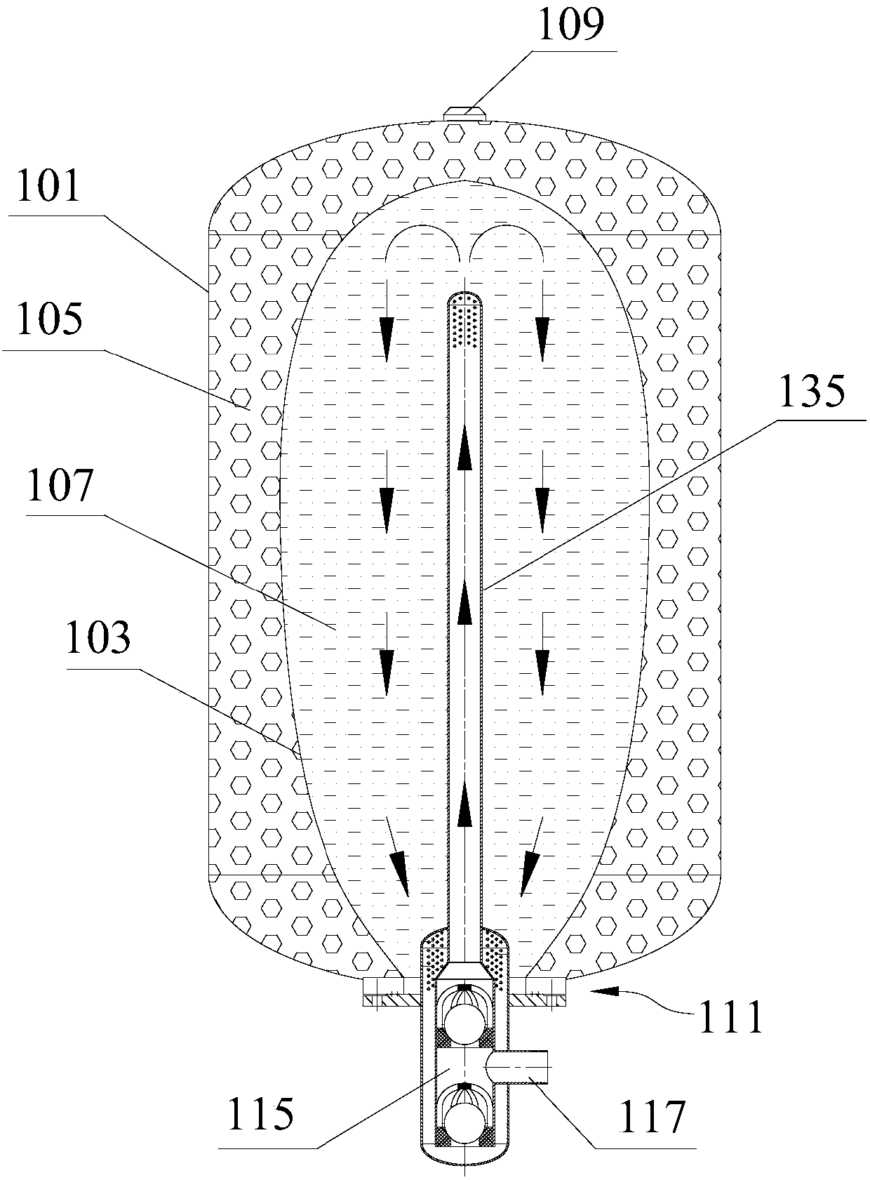
[0034] Embodiment 1, with reference to Figure 1 to Figure 2 shown.
[0035] The present embodiment provides a bag-type air pressure tank, comprising a tank body 101 and an elastic air bag 103, the elastic air bag 103 is arranged in the tank body 101 and divides the inside of the tank body 101 into an air chamber 105 and a water chamber 107, and the tank body 101 An air filling port 109 communicating with the air chamber 105 and a water inlet and outlet 111 communicating with the water chamber 107 are respectively arranged on the top, and the water inlet and outlet 111 is provided with a water inlet and outlet structure 113 .
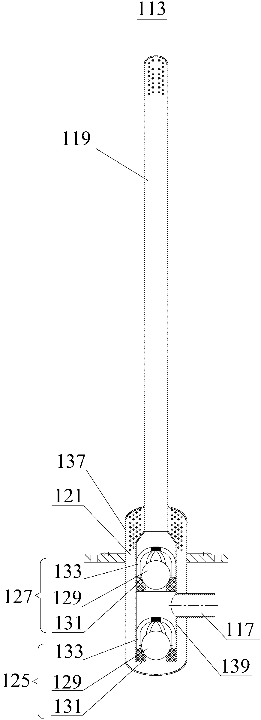
[0036] Wherein, the water inlet and outlet structure 113 includes a water inlet and outlet joint 115 installed at the water inlet and outlet 111 of the tank body 101 .
[0037] The water inlet and outlet joint 115 has a parallel single interface 117 for connecting with the tap water pipe network. The inside of the water inlet and outlet joint 115 is pr...
Embodiment 2
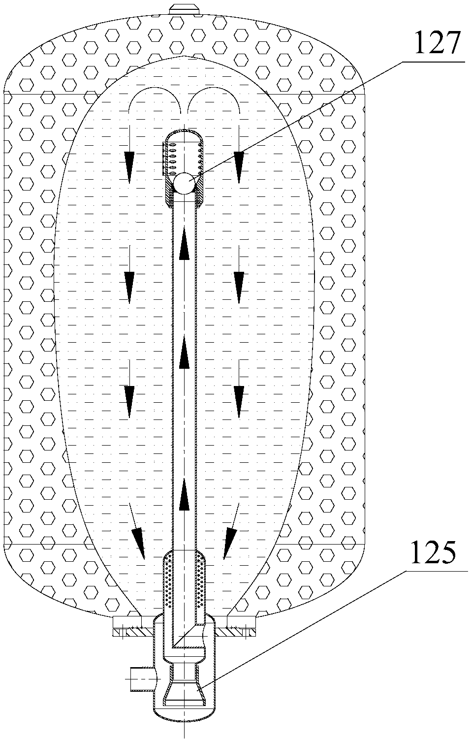
[0059] Embodiment 2 refers to Figure 3-Figure 5 shown.
[0060] The implementation principle of the bag-type air tank provided by the embodiment of the present invention is basically the same as that of Embodiment 1. For a brief description, reference may be made to the corresponding content in Embodiment 1 for the parts not mentioned in this embodiment.
[0061] In this embodiment, the water inlet one-way valve 127 is arranged at the water outlet end of the inner pipe 135, and the water outlet one-way valve 125 is arranged in the water inlet and outlet joint 115, the water inlet one-way valve 127 is a gravity valve, and the water outlet one-way valve 125 is Duckbill valve.
[0062] In this embodiment, the tee 139 is removed from the water inlet and outlet joint 115, and the return water collection tank shell 137 is transformed into a structure with a public water chamber 107 and a water outlet channel 121, and the parallel single interface 117 is arranged in the return wate...
Embodiment 3
[0067] Embodiment 3 refers to Figure 6 and Figure 7 shown.
[0068] The implementation principle of the bladder-type air tank provided by the embodiment of the present invention is basically the same as that of Embodiment 2. For a brief description, reference may be made to the corresponding content in Embodiment 1 for the parts not mentioned in this embodiment.
[0069] Such as Figure 6 and Figure 7 As shown, in this embodiment, the water inlet one-way valve 127 is arranged at the water outlet end of the inner pipe 135 , and the water outlet one-way valve 125 is arranged in the water inlet and outlet joint 115 . Both the water inlet check valve 127 and the water outlet check valve 125 are duckbill valves.
[0070] The difference between this embodiment and Embodiment 2 is that the water outlet one-way valve 125 is a duckbill valve, and the rotary spray water distributor 143 is not provided, and the duckbill valve is connected to the water outlet end of the inner pipe ...
PUM
 Abstract
Description
Claims
Application Information
 - R&D Engineer
- R&D Manager
- IP Professional
- Industry Leading Data Capabilities
- Powerful AI technology
- Patent DNA Extraction
Browse by: Latest US Patents, China's latest patents, Technical Efficacy Thesaurus, Application Domain, Technology Topic.
© 2024 PatSnap. All rights reserved.Legal|Privacy policy|Modern Slavery Act Transparency Statement|Sitemap