
Cold end system of thermal power plant and controlling method of cold end system

A technology for thermal power plants and terminal controllers, used in steam/steam condensers, lighting and heating equipment, etc., to avoid cavitation problems, rational design, and unique ideas

Pending Publication Date: 2018-01-23
HANGZHOU HUADIAN ENERGY ENG
View PDF7 Cites 2 Cited by
  • Summary
  • Abstract
  • Description
  • Claims
  • Application Information

AI Technical Summary

Problems solved by technology

[0005] To sum up, there is currently no cold-end optimization system with a reasonable structure design and a unique concept that can effectively reduce the pressure of the condenser and reduce the standard coal consumption of the unit for power supply.

Method used


Image

  • Cold end system of thermal power plant and controlling method of cold end system

Examples


Embodiment Construction

[0015] The present invention will be further described in detail below in conjunction with the accompanying drawings and examples. The following examples are explanations of the present invention and the present invention is not limited to the following examples.

[0016] Example.

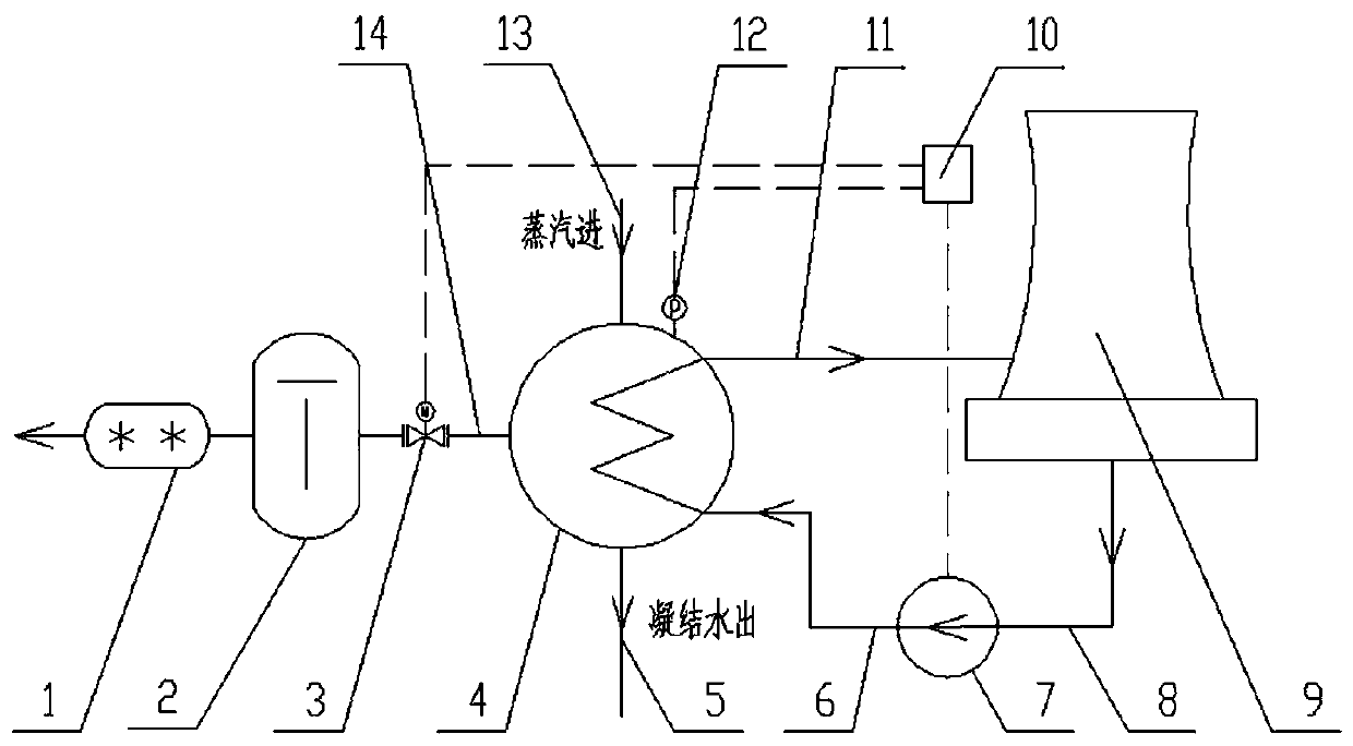
[0017] see figure 1 .

[0018] This embodiment is a cold end system of a thermal power plant, including a condenser 4, a circulating water outlet pipe 11, a cooling tower 9, a circulating water inlet tunnel 8, a variable frequency circulating pump 7, a pressure gauge 12, a steam extraction pipe 14, a Ci vacuum pump 2, electric regulating valve 3, terminal controller 10, two-stage water ring vacuum pump 1 and circulating water inlet pipe 6.

[0019] One end of the circulating water outlet pipe 11 is connected to the water side outlet of the condenser 4, the other end of the circulating water outlet pipe 11 is connected to the inlet of the cooling tower 9, and the outlet of the cooling tower 9 is c...


PUM


Abstract

The invention relates to a cold end system of a thermal power plant and a controlling method of the cold end system. The cold end system is characterized in that the cold end system comprises a condenser, a circulating water outlet pipeline, a cooling tower, a circulating water inlet channel, a frequency conversion circulating pump and a circulating water inlet pipeline; one end of the circulatingwater outlet pipeline is connected to an outlet of the water side of the condenser, and the other end of the circulating water outlet pipeline is connected to an inlet of the cooling tower; the outlet of the cooling tower is connected with one end of the circulating water inlet channel, and the other end of the circulating water inlet channel is connected with an inlet of the frequency conversioncirculating pump; one end of the circulating water inlet pipeline is connected with an outlet of the frequency conversion circulating pump, and the other end of the circulating water inlet pipeline is connected with an inlet of the water side of the condenser; and a steam inlet pipeline and a condensed water outlet pipeline are connected to the condenser. According to the cold end system of the thermal power plant, design is reasonable, and conception is unique; and through comprehensive consideration of the cold end system of the thermal power plant and optimized design of the condenser, a circulating water pump, the cooling tower and a vacuum pumping system, pressure of the condenser can be effectively reduced, and standard coal consumption of power supply of a unit can be reduced.

Description

technical field [0001] The invention relates to a cold-end system optimization structure and method, in particular to a thermal power plant cold-end system and its control method, which are mainly used in thermal power plants. Background technique [0002] For thermal power generation units, the operation of the cold-end system has a major impact on the thermal economy of the unit, and the condenser pressure is an important index parameter. Studies have shown that for every 1kPa increase in the condenser pressure, the standard coal consumption of the unit for power supply will increase by 3g / (kW·h). With the long-term operation of the unit, due to problems such as equipment aging, scaling and wear, the parameters of the circulating water are not up to standard, the cooling capacity of the cooling tower is insufficient, the heat exchange tube bundle of the condenser leaks, and the vacuum of the condenser cannot be maintained. , the final result is that the pressure of the co...

Claims


Application Information

Patent Timeline
Patent Type & Authority Applications(China)
IPC IPC(8): F28B11/00F28B9/00F28B9/10
Inventor 胡清林茂朱文中许青云蒋文
Owner HANGZHOU HUADIAN ENERGY ENG
Learn More