Dielectric lens and cleave antenna

A dielectric lens and lens technology, applied in the direction of antennas, antenna arrays, antenna parts, etc., to achieve the effect of thickness reduction and thickness reduction

Active Publication Date: 2018-01-23
HUAWEI TECH CO LTD
View PDF5 Cites 11 Cited by
  • Summary
  • Abstract
  • Description
  • Claims
  • Application Information

AI Technical Summary

Problems solved by technology

A feasible solution is to set an electromagnetic lens in the split antenna to increase the system capacity, how to design the electromagnetic lens becomes a technical bottleneck

Method used


Image

  • Dielectric lens and cleave antenna
  • Dielectric lens and cleave antenna
  • Dielectric lens and cleave antenna

Examples


Embodiment Construction

[0057] The following will clearly and completely describe the technical solutions in the embodiments of the present invention with reference to the accompanying drawings in the embodiments of the present invention. Obviously, the described embodiments are some of the embodiments of the present invention, but not all of them. Based on the embodiments of the present invention, all other embodiments obtained by persons of ordinary skill in the art without creative efforts fall within the protection scope of the present invention.

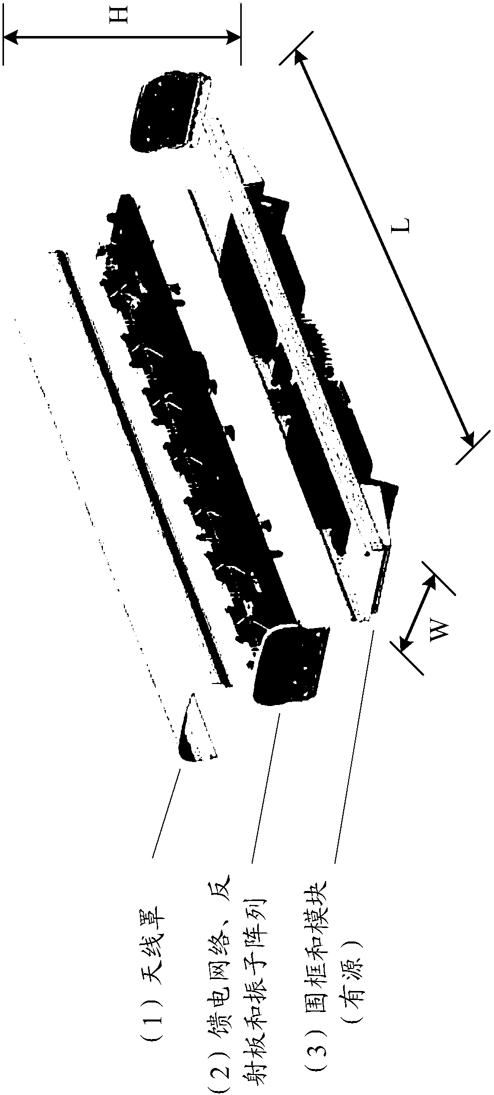
[0058] figure 1 is a schematic diagram of a conventional antenna. figure 1 The traditional antenna includes: (1) radome; (2) feed network, reflector and dipole array; (3) surrounding frame and module (active). in addition, figure 1 The dimensions of the antenna are also shown in , which are width (W), thickness (H) and length (L), respectively.

[0059] With the substantial increase in the number of users, the current network is facing problems such...


PUM


Abstract

The invention provides a dielectric lens. The dielectric lens is a lenticular lens or ellipsoidal lens with a quasi-elliptical cross-sectional profile. The dielectric lens formed by piling up a numberof unit bodies. Through the permittivity distribution of the unit bodies in the dielectric lens, a quasi-elliptical non-plane wave in the minor axis direction becomes a plane wave through the dielectric lens. The unit bodies of the dielectric lens are prepared by extrusion, injection molding, stamping, CNC machining or a 3D printing technology. The assembly of the unit bodies can be glue joint, welding, structure clamp connection or direct 3D printing. When the dielectric lens is applied to a cleave antenna, the system capacity of a communication system can be improved. Compared with a traditional cylindrical luneberg lens antenna, the cleave antenna has reduced lens thickness.

Description

technical field [0001] Embodiments of the present invention relate to the communication field, and more specifically, relate to a dielectric lens and a split antenna. Background technique [0002] Traditional antennas used in the communications industry, such as figure 1 As shown, it usually consists of three main parts: (1) radome; (2) feed network, reflector and oscillator array; (3) enclosure and module (active). With the substantial increase of the number of users, the current network is facing the problem of tight system capacity. [0003] The split antenna technology is dedicated to improving the system capacity and communication quality of the mobile communication system, and it is a technical solution with good application prospects. A feasible solution is to set an electromagnetic lens in the split antenna to increase the system capacity, and how to design the electromagnetic lens becomes a technical bottleneck. Contents of the invention [0004] An embodiment ...

Claims


Application Information

Patent Timeline
Patent Type & Authority Applications(China)
IPC IPC(8): H01Q1/36H01Q1/50H01Q19/06H01Q19/10
CPCH01Q1/246H01Q19/062H01Q19/108H01Q15/08H01Q21/062H01Q1/42H01Q15/16H01Q21/20
Inventor 胡邦红黎良元戴作杏李磊章园红张润孝张跃江
Owner HUAWEI TECH CO LTD
Why Eureka
Try Eureka