Truss type wing leading edge camber continuous changing structure

A wing leading edge and truss-type technology, applied in the direction of wing adjustment, etc., can solve the problems of small additional resistance and aerodynamic efficiency decline, and achieve the effects of reducing flight resistance, improving aerodynamic performance and increasing range

Active Publication Date: 2018-01-26
SHENYANG AIRCRAFT DESIGN INST AVIATION IND CORP OF CHINA
View PDF4 Cites 16 Cited by
  • Summary
  • Abstract
  • Description
  • Claims
  • Application Information

AI Technical Summary

Problems solved by technology

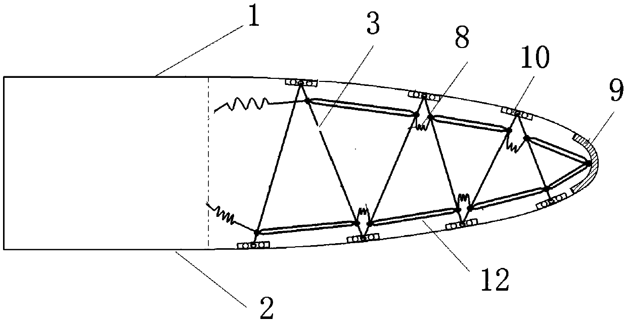
[0004] Purpose of the present invention: in order to solve the above problems, the present invention proposes a truss-type wing leading edge continuously variable camber structure, which changes the camber of the wing leading edge and adjusts the shape of the wing leading edge through the thermal deformation of the temperature-controlled memory alloy rod assembly Smoothly change the shape of the airfoil, which can generate less additional drag while providing the same lift as the traditional leading-edge flap, and solve the problem of the aerodynamic efficiency decrease when the leading-edge flap of the existing aircraft is deflected

Method used


Image

  • Truss type wing leading edge camber continuous changing structure
  • Truss type wing leading edge camber continuous changing structure
  • Truss type wing leading edge camber continuous changing structure

Examples


Embodiment Construction

[0025] In order to make the objectives, technical solutions and advantages of the present invention clearer, the technical solutions in the embodiments of the present invention will be described in more detail below in conjunction with the drawings in the embodiments of the present invention. In the drawings, the same or similar reference numerals denote the same or similar elements or elements having the same or similar functions throughout. The described embodiments are some, but not all, embodiments of the invention. The embodiments described below by referring to the figures are exemplary and are intended to explain the present invention and should not be construed as limiting the present invention. Based on the embodiments of the present invention, all other embodiments obtained by persons of ordinary skill in the art without creative efforts fall within the protection scope of the present invention. Embodiments of the present invention will be described in detail below ...


PUM


Abstract

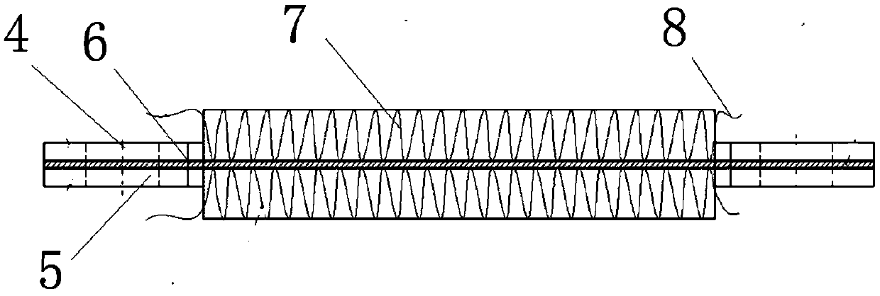
The invention discloses a truss type wing leading edge camber continuous changing structure, and belongs to the field of design of aircraft wing structure. The structure includes that a wing leading edge cavity enclosed by upper flexible skin and lower flexible skin is internally provided with a plurality of trusses, two ends of each truss are slidingly connected with the upper flexible skin and the lower flexible skin, and the plurality of trusses are mutually hinged and can be linked; each memory alloy rod assembly is composed of a first memory alloy rod and a second memory alloy rod, the first memory alloy rod is heated to extend, and the second memory alloy rod is heated to shorten; the memory alloy rod assemblies are arranged between each two adjacent trusses, and are respectively andevenly distributed along the upper flexible skin and the lower flexible skin; the memory alloy rod assemblies are heated to deform to drive the trusses to move, and make the upper flexible skin and the lower flexible skin deformed. The structure has the advantages of simple mechanism principle, direct stress efficacy and high reliability, and the wing leading edge deformation is flexible, controllable, reversible and repeated intelligent deformation which can continuously change the camber of the wing.

Description

technical field [0001] The invention belongs to the technical field of aircraft wing structure design, and in particular relates to a truss-type wing leading edge continuously variable camber structure. Background technique [0002] The front of the aircraft wing is usually equipped with leading edge flaps, which are used to delay the occurrence of stall when the aircraft is flying at a high angle of attack. At the same time, the leading edge flap can increase the maximum lift coefficient and improve the aerodynamic performance of the aircraft. [0003] The leading edge flap of the existing aircraft is connected to the wing box by a hinge, and the deflection of the leading edge flap is realized through the rotation around the hinge, thereby adjusting the aerodynamic force of the wing and controlling the flight attitude of the aircraft. When the leading-edge flap deflects, it will cause a sudden change in the shape of the wing, and the airflow is prone to separation when pas...

Claims


Application Information

Patent Timeline
Patent Type & Authority Applications(China)
IPC IPC(8): B64C3/50
Inventor 王云俊戚家亮吴斌何天闯
Owner SHENYANG AIRCRAFT DESIGN INST AVIATION IND CORP OF CHINA
Why Eureka
Try Eureka