Connecting structure of steel tank ditch and glass daylighting roof and connecting method thereof

A technology for connecting structures and lighting roofs, which is applied in building structures, roofs, buildings, etc., can solve the problems of increasing the difficulty of engineering construction, increasing the cost, and being non-adjustable, so as to improve the scope of application and versatility, improve safety, and reduce The effect of cost

Pending Publication Date: 2018-01-26
SHENZHEN SANXIN FACADE ENG
View PDF15 Cites 0 Cited by
  • Summary
  • Abstract
  • Description
  • Claims
  • Application Information

AI Technical Summary

Problems solved by technology

[0002] With the construction of a large number of large public buildings and the rapid development of construction technology, the span of buildings is getting larger and larger. With the continuous updating of architectural concepts, architects are increasingly pursuing artistic effects and personalization; in order to achieve this special Requirements, usually through various special-shaped structures to reflect the intention of the design; especially large public buildings such as airport terminals, convention centers, shopping malls, etc., all use a combination of large-span, complex space steel structures and daylighting glass as the roof structure system (ie Glass lighting roof); glass lighting roof has the advantages of transparency, light weight, energy saving, etc., and combined with steel structure modeling, it can realize plane, spherical, saddle surface and other appearance styles, so it is widely used in modern buildings, but these glass lighting roofs The angle of the structure when it is combined with the steel channel gutter is not adjustable, and it cannot be applied to the needs of all different inclinations, so that the structure of the glass skylight tends to be diversified. However, these structural systems not only satisfy the visual effect, but also Greatly increased the construction difficulty of the project and increased the cost

Method used


Image

  • Connecting structure of steel tank ditch and glass daylighting roof and connecting method thereof
  • Connecting structure of steel tank ditch and glass daylighting roof and connecting method thereof

Examples


Embodiment 1

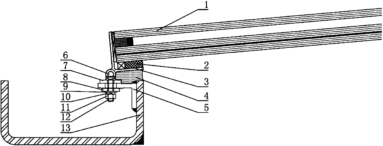
[0030] Such as Figure 1 to Figure 2 As shown, the connection structure between the steel channel gutter and the glass daylighting roof shown in this embodiment includes the L-shaped aluminum alloy sub-frame 3 bonded together with the glass daylighting roof, the base 7 and the steel channel gutter 13 The angle steel 5, the base 7 and the L-shaped aluminum alloy sub-frame 3 are connected in a rotatable manner, the angle steel 5 is fixedly connected with the base 7, so that the steel channel water ditch 13 is arranged under the glass lighting roof, and the L-shaped The aluminum alloy sub-frame 3 can rotate relative to the steel channel water ditch 13, and then the inclination angle of the glass daylighting roof can be adjusted under the condition that the steel channel water channel 13 is horizontal.

Embodiment 2

[0032] Such as Figure 1 to Figure 2 As shown, the connection structure between the steel channel gutter and the glass daylighting roof in this embodiment includes the L-shaped aluminum alloy sub-frame 3 bonded together with the glass daylighting roof, the base 7 and the inner side of the steel channel gutter 13 welded The angle steel 5 at the upper end, the base 7 are movably connected with the L-shaped aluminum alloy sub-frame 3, and the angle steel 5 and the base 7 are fixedly connected together by a bolt assembly, so that the steel channel water ditch 13 is arranged under the glass daylighting roof. Through this connection structure, the The L-shaped aluminum alloy sub-frame 3 can rotate relative to the steel channel gutter 13, and then the inclination angle of the glass lighting roof can be adjusted under the condition that the steel channel gutter 13 is level.

[0033] Among them, the glass used in the glass lighting roof is tempered hollow laminated glass 1, and the end...

Embodiment 3

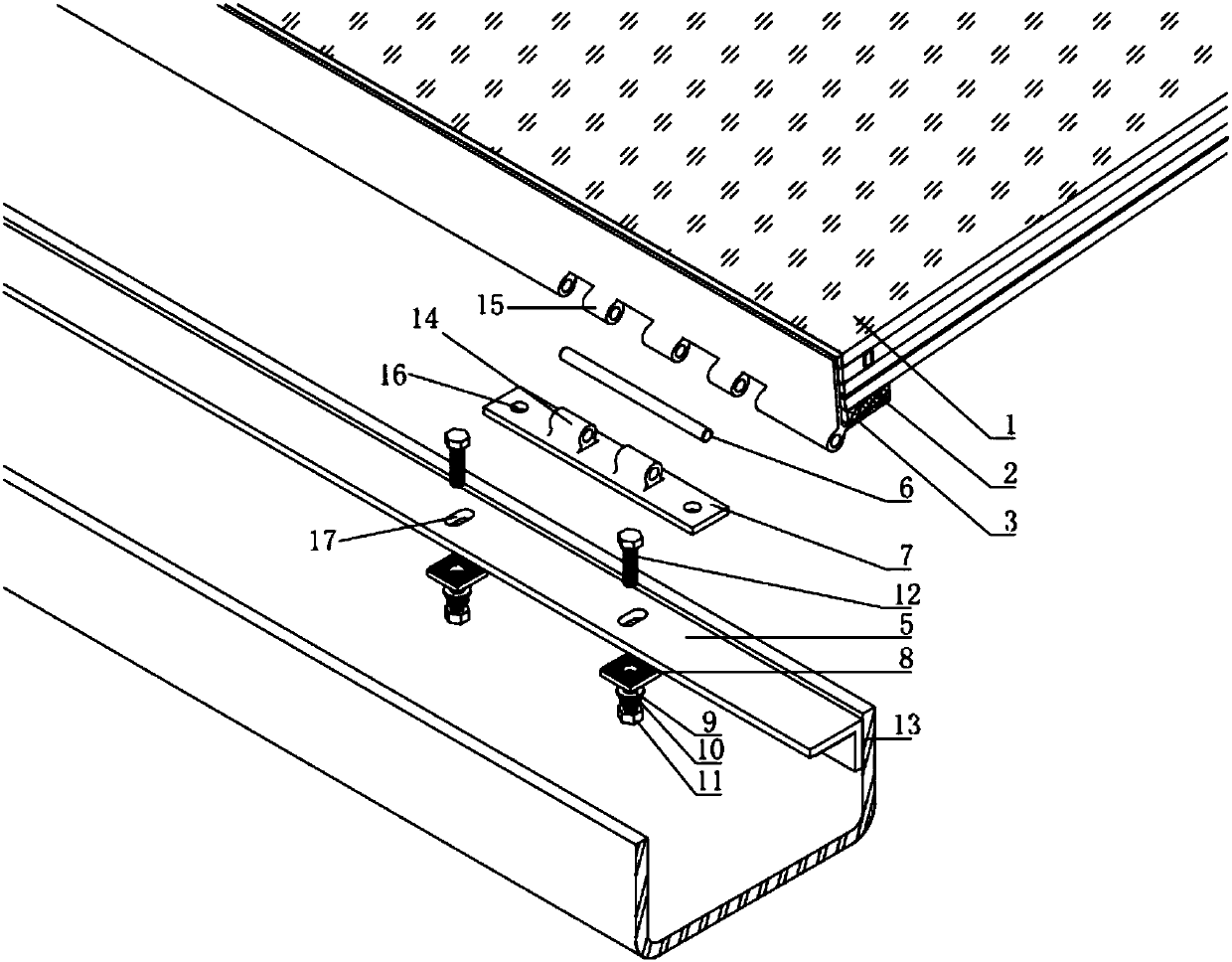
[0039] A connection method using the connection structure of embodiment 2, comprising the following steps:

[0040] S1. Bond the L-shaped aluminum alloy sub-frame to the end of the tempered hollow laminated glass in the glass lighting roof;

[0041] S2. Fix the T-shaped aluminum alloy base to the upper end of the angle steel on the steel channel gutter through the bolt assembly;

[0042] S3. After the glass daylighting roof is engaged with the first penetration part on the T-shaped aluminum alloy base through the second penetration part at the outer lower end of the L-shaped aluminum alloy sub-frame 3, insert the stainless steel pin shaft into the first penetration part and the second penetration part In the hole on the top, so that the two can be rotatably connected together;

[0043] S4. When adjusting the angle between the glass lighting roof and the steel channel gutter to the design requirements, fill the silicone weather-resistant sealant between the stainless steel ang...


PUM


Abstract

The invention discloses a connecting structure of a steel tank ditch and a glass daylighting roof. The connecting structure comprises an L-shaped auxiliary frame adhered with the glass daylighting roof together, a base and steel angles arranged on the steel tank ditch, wherein the base is movably connected with the L-shaped auxiliary frame; the steel angles are fixedly connected with the base; andthe steel tank ditch is arranged under the glass daylighting roof. The inclination angle of the glass daylighting roof is adjustable through the connecting structure, the connecting structure is applicable of buildings with different requirements on the inclination angles, the application range and universality of the glass dayilghting roof are improved, and the connecting structure are convenient for construction and cost reduction.

Description

technical field [0001] The invention relates to the technical field of architecture, in particular to the closing connection of a curved glass daylighting roof, that is, a connection structure between a steel channel gutter and a glass daylighting roof and a connection method thereof. Background technique [0002] With the construction of a large number of large public buildings and the rapid development of construction technology, the span of buildings is getting larger and larger. With the continuous updating of architectural concepts, architects are increasingly pursuing artistic effects and personalization; in order to achieve this special Requirements, usually through various special-shaped structures to reflect the intention of the design; especially large public buildings such as airport terminals, convention centers, shopping malls, etc., all use a combination of large-span, complex space steel structures and daylighting glass as the roof structure system (ie Glass l...

Claims


Application Information

Patent Timeline
IPC IPC(8): E04D13/072
Inventor 杨云许伟东蔡广剑
Owner SHENZHEN SANXIN FACADE ENG
Why Eureka
Try Eureka