Hydraulic system

A technology for hydraulic systems and hydraulic actuators, applied in the directions of fluid pressure actuating system components, fluid pressure actuating devices, servo motors, etc., can solve problems such as troublesome, inoperable by non-transferred personnel, and achieve the change of working flow and improving operation. Efficiency, control stable and reliable effect

Inactive Publication Date: 2018-01-26
LIUGONG CHANGZHOU MACHINERY +2
View PDF8 Cites 3 Cited by
  • Summary
  • Abstract
  • Description
  • Claims
  • Application Information

AI Technical Summary

Problems solved by technology

Not only is it troublesome, it is also inoperable for non-displaced personnel

Method used


Image

  • Hydraulic system

Examples


Embodiment Construction

[0015] The specific implementation will be described below in conjunction with the accompanying drawings.

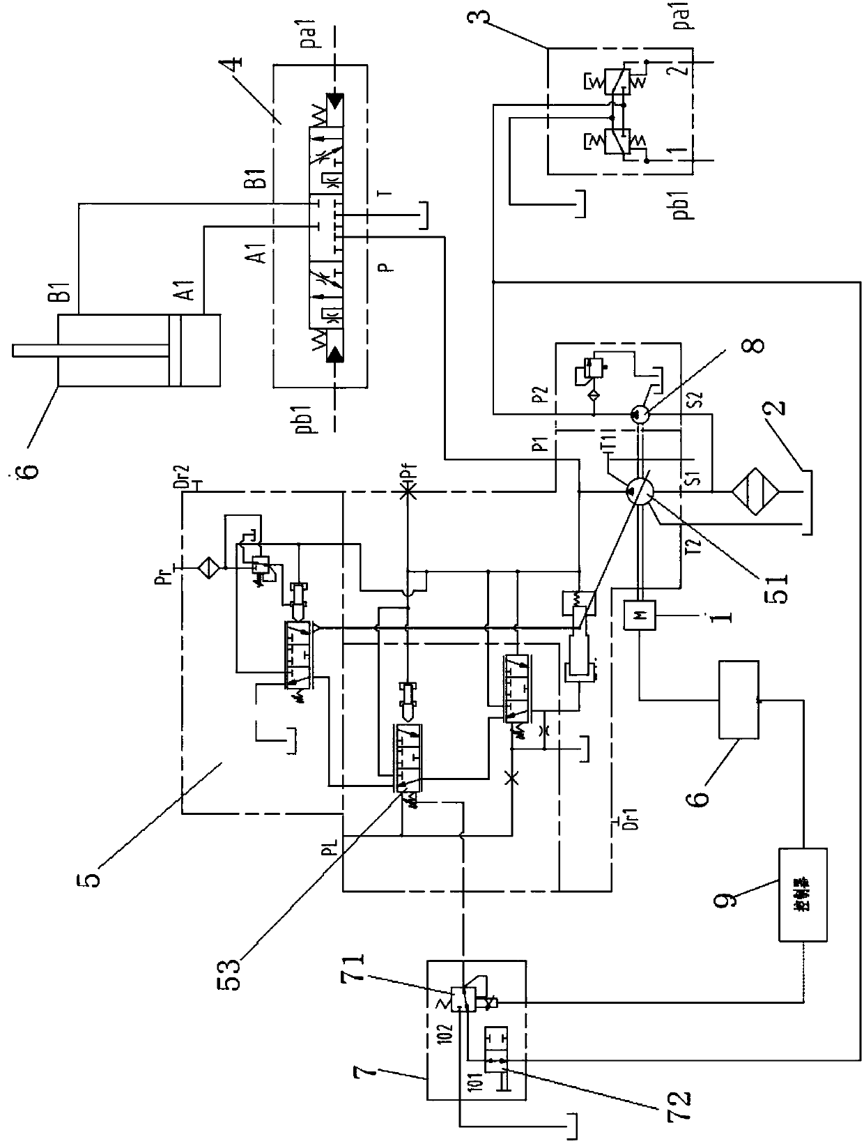
[0016] The hydraulic system in this embodiment is as figure 1 As shown, it includes attachment hydraulic actuators, control valve group 7, multi-way valve 4, variable displacement pump 5, pilot valve 3, pilot pump 8, and controller 9.

[0017] The attachment hydraulic actuator may be the attachment cylinder 6, or a hydraulic motor or other devices that use hydraulic energy as the driving energy.

[0018] There are multiple control valves in the multi-way valve 4, which are used to control different hydraulic actuators, including hydraulically controlled attachment control valves for controlling attachments.

[0019] The variable pump 5 includes a load sensing valve 53 and a plunger pump 51. The load feedback oil circuit PL interface of the variable pump 5 is connected to the left end of the load sensing valve 53, and the pump port of the plunger pump 51 is connected to ...


PUM


Abstract

The invention relates to a hydraulic system and aims at solving the problem that the working flow is irrelevant to the rotating speed of an engine when the flow of an existing load sensitive hydraulicsystem is unsaturated. The provided hydraulic system comprises an accessory hydraulic actuation element, an accessory control valve, a variable pump, the engine, an accessory control device, a pilotoil source, an electric proportional pressure reducing valve, a controller and a speed reducer, wherein the output end of the controller is connected with the electric control end of the electric proportional pressure reducing valve; the speed sensor is used for detecting the rotating speed of the engine and is connected with the controller; the output end of the electric proportional pressure reducing valve is connected with the control end of a load sensitive valve of a plunger pump; the input end of the electric proportional pressure reducing valve is connected with the pilot oil source through a stop valve; the controller outputs control voltage according to a corresponding preset value by referencing the rotating speed, detected by the speed sensor, of the engine and enables the electric proportional pressure reducing valve to output a pressure signal corresponding to a pressure value. The hydraulic system disclosed by the invention has the characteristics of simplicity and convenience in operation; the hydraulic system is convenient for an operator to operate, and the operation efficiency can be improved according to actual conditions.

Description

technical field [0001] The invention relates to a hydraulic system, more specifically, to a hydraulic system that can control and adjust the flow rate according to the engine speed. Background technique [0002] When the flow rate of the existing load-sensitive hydraulic system excavator is not saturated, the working flow rate of the hydraulic system has nothing to do with the engine speed. After the component manufacturer sets the differential pressure through the orifice, the working flow of the system reaches the set differential pressure through the orifice, and the main pump will no longer increase the displacement. At this time, if you want to improve the efficiency of a single action of the excavator. It is necessary to reset the differential pressure signal of the main pump LS port (load sensing control spool). And after the size is set, if you want to change it, you have to adjust it again. Not only troublesome, non-displaced personnel cannot operate. Contents ...

Claims


Application Information

Patent Timeline
Patent Type & Authority Applications(China)
IPC IPC(8): F15B21/08F15B11/17F15B13/06
Inventor 陈向明刘万天石子贡
Owner LIUGONG CHANGZHOU MACHINERY
Why Eureka
Try Eureka