Polarity reversal driving method of liquid crystal display device and source driver

A liquid crystal display and source driver technology, applied to static indicators, instruments, etc., can solve the problems of image quality reduction, interference noise at the top and bottom of the pattern, etc.

Active Publication Date: 2018-01-26
HIMAX TECH LTD
View PDF6 Cites 8 Cited by
  • Summary
  • Abstract
  • Description
  • Claims
  • Application Information

AI Technical Summary

Problems solved by technology

Although it consumes less power than the dot inversion driving method, the N-line inversion driving method tends to cause horizontal dark lines, thus reducing image quality

Method used


Image

  • Polarity reversal driving method of liquid crystal display device and source driver
  • Polarity reversal driving method of liquid crystal display device and source driver
  • Polarity reversal driving method of liquid crystal display device and source driver

Examples


Embodiment Construction

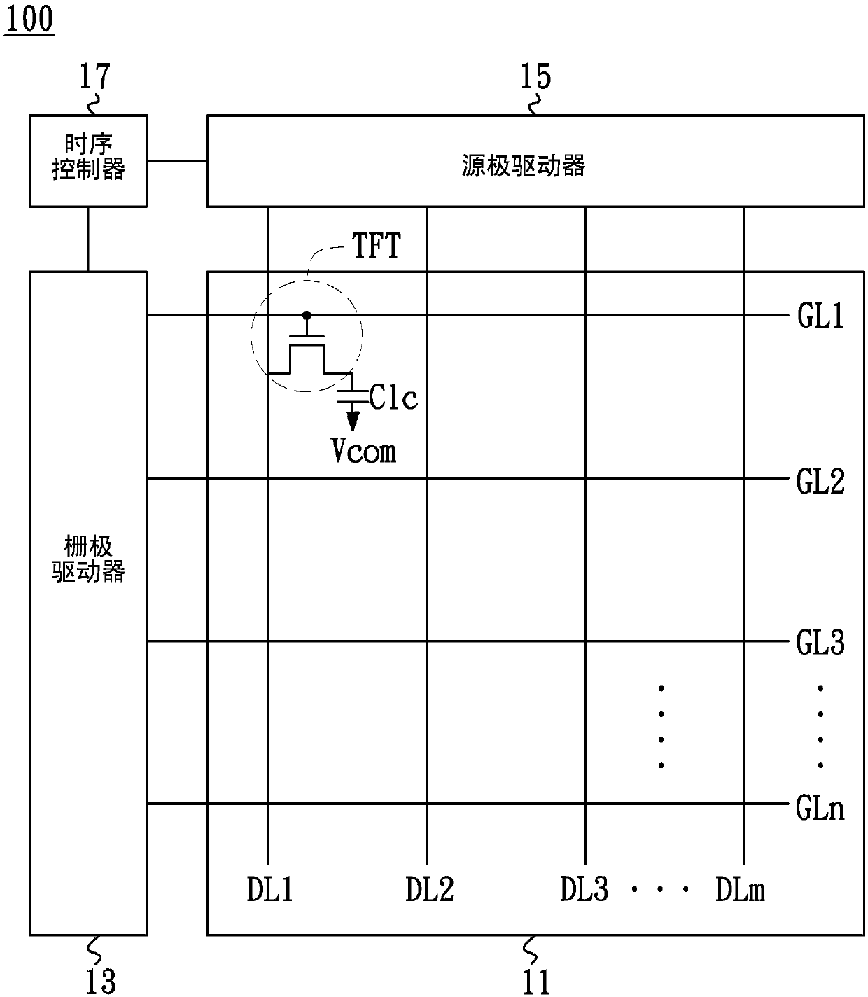
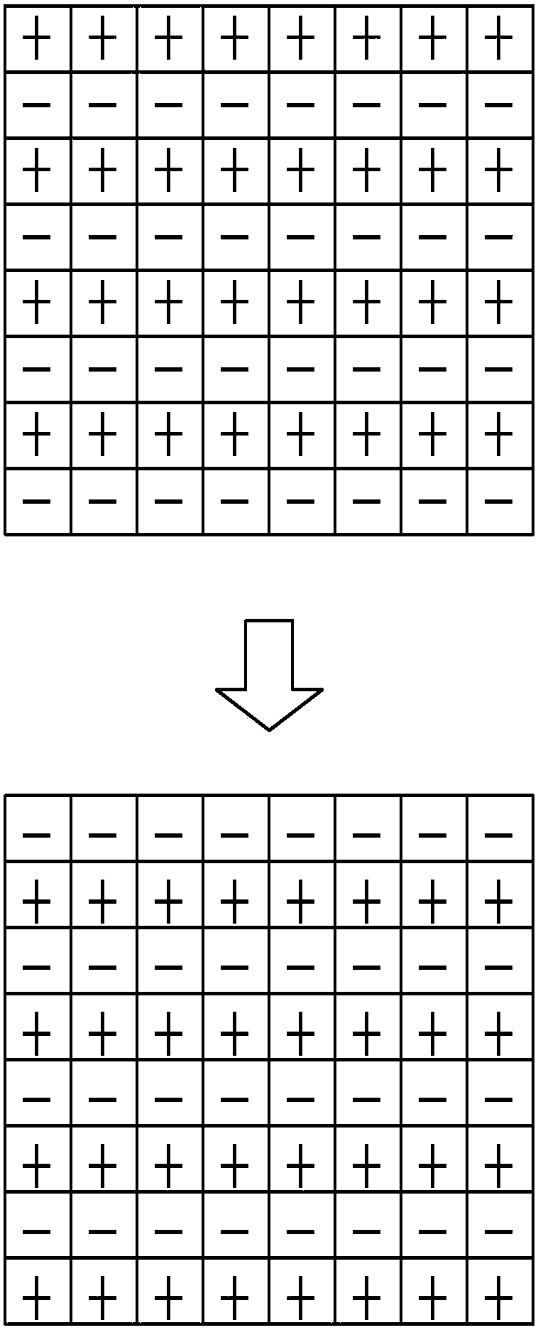
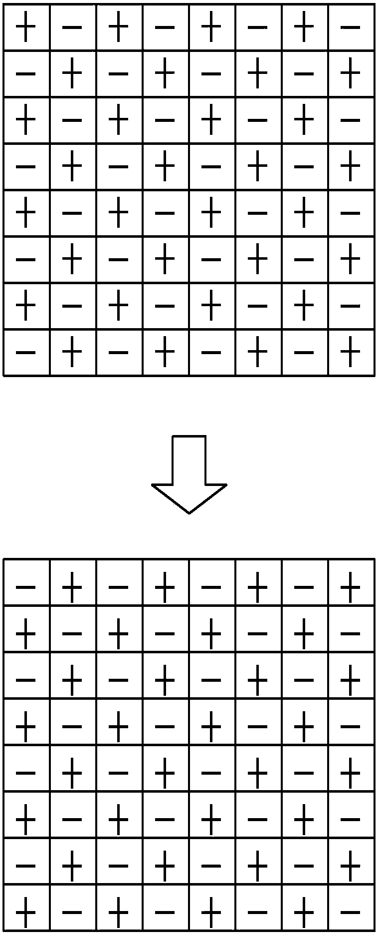
[0043] Figure 5 The flow chart showing the polarity inversion (polarity inversion) driving method of the liquid crystal display 100 according to the embodiment of the present invention, the system architecture of the liquid crystal display 100 follows figure 1 system block diagram. Figure 6 to Figure 9 A simplified schematic diagram showing a polarity inversion driving method of the liquid crystal display 100 according to an embodiment of the present invention illustrates the pixel polarities of the first, third, fifth and seventh frames respectively. The pixel polarities of the second, fourth, sixth and eighth frames are omitted and not shown, wherein the pixel polarity of the second frame is opposite to that of the first frame ( Figure 6 ), the pixel polarity of the fourth frame is opposite to that of the third frame ( Figure 7 ), the pixel polarity of the sixth frame is opposite to that of the fifth frame ( Figure 8 ), the pixel polarity of the eighth frame is oppos...


PUM


Abstract

The invention relates to a polarity reversal driving method of a liquid crystal display device and a source driver. During a same frame of display period, a polarity sequence of pixel groups of a plurality of gate lines is reversed, so that the positions of the pixel groups after polarity sequence reversing are distributed in the whole frame uniformly in a space domain. The positions of the pixelgroups after polarity sequence reversing are change at a one-frame interval, so that balanced distribution of the positions of the pixel groups is realized in a time domain.

Description

technical field [0001] The invention relates to a polarity inversion driving method of a liquid crystal display, in particular to a polarity inversion driving method with balanced distribution in space domain and time domain. Background technique [0002] Liquid crystal display (LCD) has the advantages of light weight, low power consumption and no radiation, so it is widely used in various electronic products, such as desktop computers, tablet computers, mobile phones, etc., as output display. [0003] figure 1 A system block diagram of the liquid crystal display 100 is shown. The gate lines GL1 ˜GLn and the data lines DL1 ˜DLm intersect each other to define a plurality of pixels arranged in a matrix on the liquid crystal panel 11 . A thin film transistor TFT and a liquid crystal capacitor Clc are formed in each pixel, serving as a switch and a liquid crystal cell respectively. The voltage difference between the pixel electrode (pixel electrode) and the common voltage (Vc...

Claims


Application Information

Patent Timeline
IPC IPC(8): G09G3/36
Inventor 朱育杉蔡政哲郑伊容
Owner HIMAX TECH LTD
Why Eureka
Try Eureka