
Dipole gas discharge tube structure

A technology of gas discharge tube and discharge tube, which is applied in the direction of circuits, electrical components, spark gaps, etc., can solve the problems of internal structure deformation, melting, and electrode thermal deformation of the tube body, so as to ensure consistency, improve stability, and extend service life The effect of longevity

Active Publication Date: 2018-01-26
JIANGSU DONGGUANG ELECTRONICS
View PDF3 Cites 0 Cited by
  • Summary
  • Abstract
  • Description
  • Claims
  • Application Information

AI Technical Summary

Problems solved by technology

[0003] The purpose of the present invention is to solve the insufficient amount of electronic powder in the tube body of the gas discharge tube. When subjected to the impact of high current, the metal discharge of the discharge electrode will be generated, causing the electrode to be deformed or even melted by heat, and the internal structure of the tube body is deformed, which affects the gas discharge. In order to solve the problem of the stability and life of the tube, a diode gas discharge tube with an optimized structure design can meet the direct lightning strike 10 / 350μs impulse current waveform of 50KA

Method used


Image

  • Dipole gas discharge tube structure
  • Dipole gas discharge tube structure

Examples


Embodiment Construction

[0020] Preferred embodiments of the present invention will be described in more detail below with reference to the accompanying drawings. Although preferred embodiments of the invention are shown in the drawings, it should be understood that the invention may be embodied in various forms and should not be limited to the embodiments set forth herein.

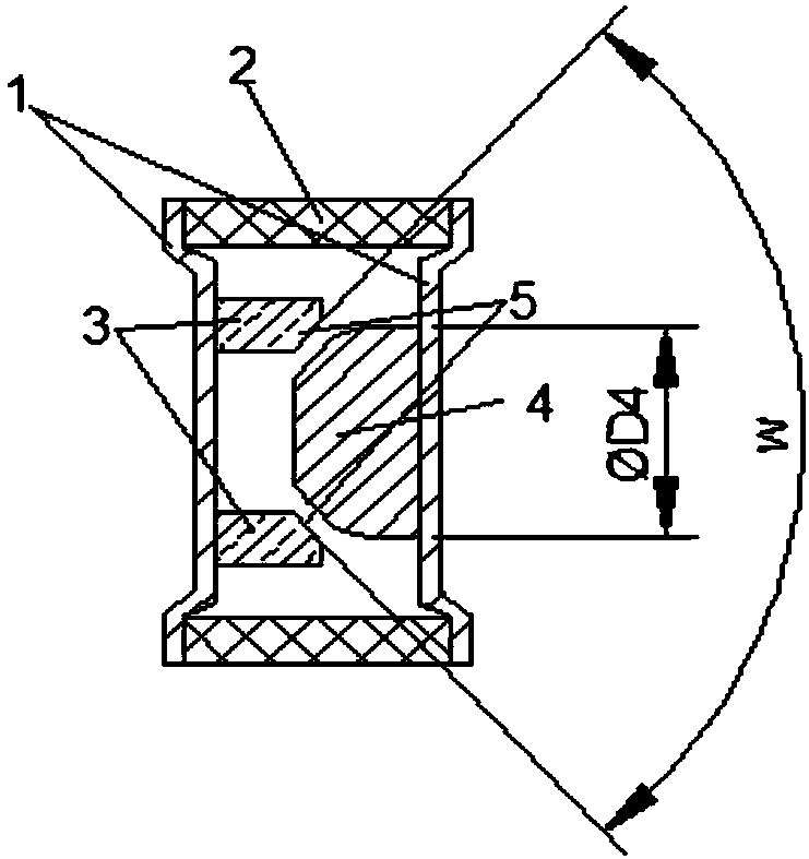
[0021] The new gas discharge diode consists of the following parts:

[0022] 1. Two flat electrodes;

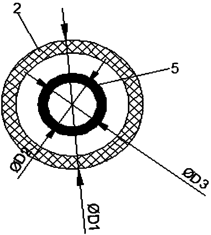
[0023] 2. One ceramic tube;

[0024] 3. One ring electrode, the inner diameter of the ring electrode discharge surface is ΦD2, and the outer diameter of the ring electrode discharge surface is ΦD3;

[0025] 4. One needle electrode, the diameter of the needle electrode is ΦD4;

[0026] The ring electrode and the needle electrode are designed with a curved surface, and the area of ​​the discharge surface is S: S=wπ(D3 / 2)2 / 360-wπ(D2 / 2)2 / 360; where D2 is the inner diameter of the discharge surface of the ring electrode 3; D3 is ...


PUM


Abstract

A dipole gas discharge tube structure provided by the present invention comprises a ceramic tube, a ring electrode, a needle electrode and two flat electrodes. The ring electrode and the needle electrode both adopt the cambered surface design and are installed on the two flat electrodes respectively, and the needle electrode is arranged at the inner side of the ring electrode correspondingly, thereby forming a cambered surface discharge surface. According to the present invention, in the tube body internal structure design, and aiming at the electrode influencing the discharge area, the optimization design is carried out, the ring electrode and the needle electrode are added, and the ring electrode adopts the cambered surface design, so that under the premise that the external size of thewhole tube and a discharge gap are constant, the discharge area is increased effectively, and the quantity of the electronic powder is increased.

Description

technical field [0001] The invention relates to the field of power distribution, and more specifically relates to the structural design and application of a gas discharge tube with two electrodes. Background technique [0002] At present, in the field of power distribution, a 3+1 structure is used for line protection in the lightning wave protection circuit, and three varistors and a ceramic gas discharge tube are used for protection. The varistor protects the loop from the live wire to the neutral wire, and the gas discharge tube protects the loop from the neutral wire to the ground wire. Because the insulation resistance of the gas discharge tube is high (≥1GΩ), it can effectively cut off the leakage current loop of the varistor to the ground, and prevent the distribution line from catching fire due to the increase of the leakage current of the varistor. For gas discharge tubes, a higher overcurrent capability is required (10 / 350μs impulse current waveform for direct ligh...

Claims


Application Information

Patent Timeline
Patent Type & Authority Applications(China)
IPC IPC(8): H01T4/10H01T1/22
Inventor 史宏斌王飞袁雪姣
Owner JIANGSU DONGGUANG ELECTRONICS
Features
  • Generate Ideas
  • Intellectual Property
  • Life Sciences
  • Materials
  • Tech Scout
  • Unparalleled Data Quality
  • Higher Quality Content
  • 60% Fewer Hallucinations
Learn More