High-efficiency kerosene stove

A high-efficiency, kerosene technology, used in the field of kerosene stoves, can solve the problems of large heat loss, large noise, and large space occupation, and achieve the effect of improving the utilization rate of heat and reducing noise.

Inactive Publication Date: 2018-01-30
许月辉
View PDF1 Cites 0 Cited by
  • Summary
  • Abstract
  • Description
  • Claims
  • Application Information

AI Technical Summary

Problems solved by technology

[0002] Currently known diesel stoves include a combustion chamber, a feeding device connected to the combustion chamber, a gas outlet pipe connected to the combustion chamber, and a slag removal device connected to the lower end of the combustion chamber. The combustion chamber is movable to divide the com

Method used


Image

  • High-efficiency kerosene stove
  • High-efficiency kerosene stove
  • High-efficiency kerosene stove

Examples


Embodiment Construction

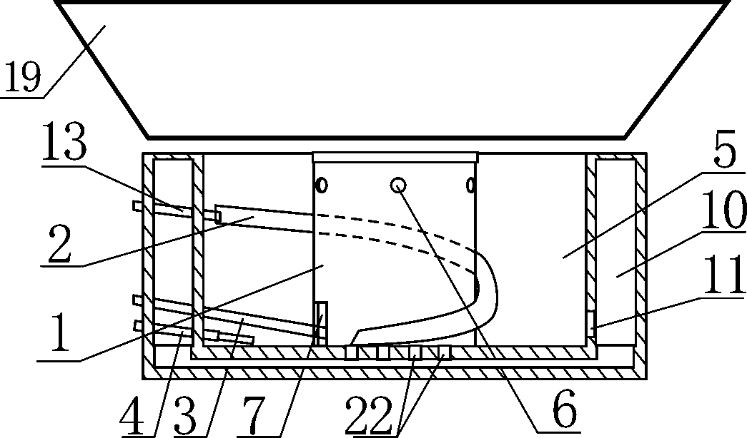
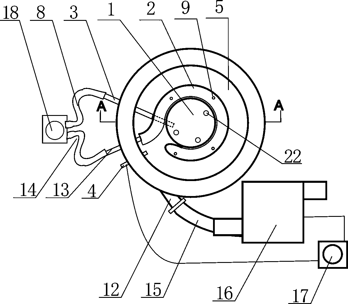
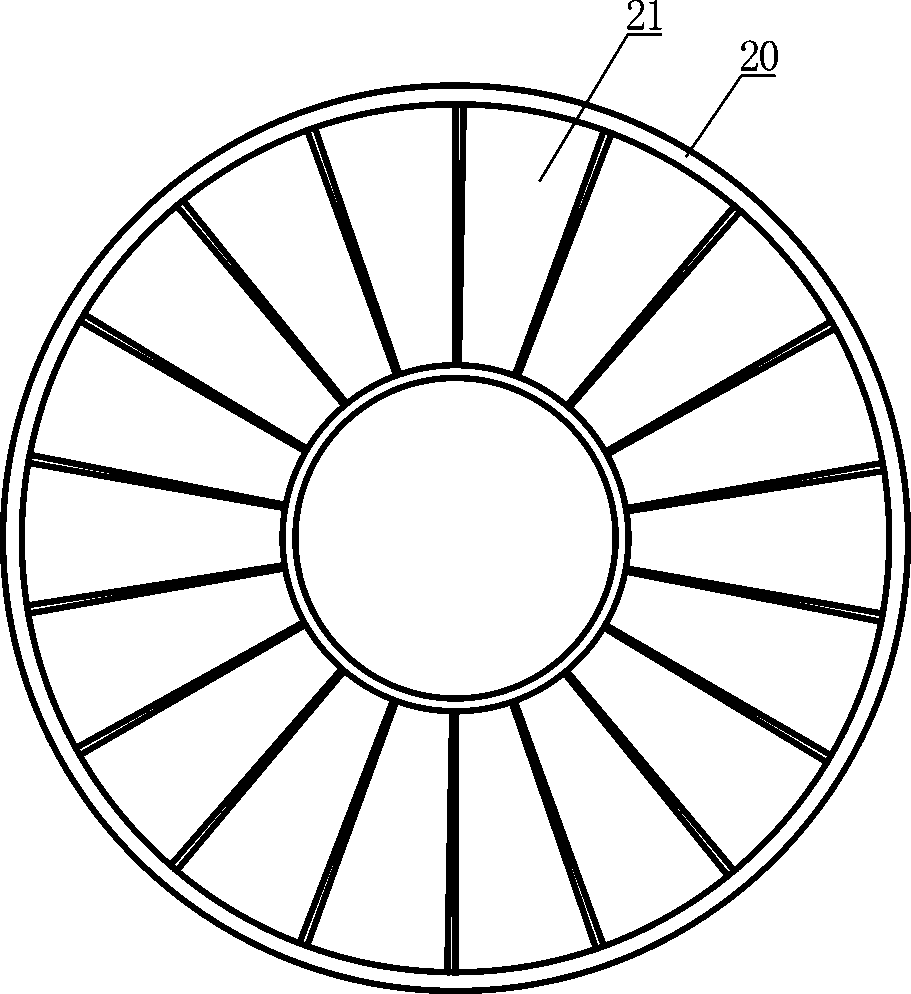
[0015] like figure 1 , 2 , 3, the high-efficiency kerosene stove includes an igniter 4, a fan 16 and a power supply 17, wherein the power supply 17 supplies power for the igniter 4 and the fan 16, and one end of the igniter 4 is located in the combustion chamber B5. It also includes combustion chamber A1, spiral pipe A2, spiral pipe B3, and a combustion chamber B5 with an open top and a closed bottom. The combustion chamber A1 is located in the combustion chamber B5. Fixed on the bottom surface of the combustion chamber B5, the upper part of the barrel wall of the combustion chamber A1 is distributed with gas through holes 6 at intervals along the circumferential direction, and the bottom side of the barrel wall of the combustion chamber A1 is provided with an introduction hole 7, and one end of the spiral tube B3 It extends into the combustion chamber A1 through the introduction hole, and the other end passes through the side wall of the combustion chamber B5 and extends out...


PUM


Abstract

The invention discloses a high-efficiency kerosene stove. The high-efficiency kerosene stove comprises a combustion chamber A, a spiral tube A, a spiral tube B, and a combustion chamber B with an opentop and a closed bottom, wherein a heat-collecting hood is arranged above the combustion chamber B; the high-efficiency kerosene stove further comprises an igniter, a fan and a power supply; the power supply supplies power to the igniting device and the fan; one end of the igniter is arranged inside the combustion chamber B and is positioned at the inner bottom of the combustion chamber B; the side wall and the bottom surface of the combustion chamber B adopt a sandwich structure; an airflow passage is formed in a cavity in the sandwich structure; the upper end of the spiral tube A is connected with a primary gasifying tube; the lower end of the spiral tube A is in contact with the inner bottom surface of the combustion chamber B; one end of the primary gasifying tube is inserted into theupper end of the spiral tube A, and a heat-insulating material is arranged between the outer wall of the primary gasifying tube and the inner wall of the spiral tube A. Due to adoption of the structure, the high-efficiency kerosene stove has the characteristics of energy conservation and environment friendliness.

Description

technical field [0001] The invention relates to a kitchen utensil, in particular to a kerosene stove. Background technique [0002] Currently known diesel stoves include a combustion chamber, a feed device connected to the combustion chamber, a gas outlet pipe connected to the combustion chamber, and a slag removal device connected to the lower end of the combustion chamber. The combustion chamber is movable to separate the combustion chamber into a primary combustion chamber. The flaps of the chamber and the reburning chamber are provided with a number of ventilation holes, and the reburning chamber is connected to the air intake pipe of the auxiliary gas, which has defects such as insufficient combustion, high noise, large heat loss, and large space occupation. Contents of the invention [0003] The object of the present invention is to provide an energy-saving and environment-friendly high-efficiency kerosene stove. [0004] To achieve the above object, the technical s...

Claims


Application Information

Patent Timeline
IPC IPC(8): F24C5/02
Inventor 许月辉
Owner 许月辉
Why Eureka
Try Eureka