
Computer room air conditioner system and computer room refrigerating control method and device

A technology for computer room air conditioners and computer rooms, applied in air conditioning systems, ventilation systems, heating methods, etc., can solve problems such as low heat exchange efficiency and corrosion of electronic components, and achieve the effect of improving cleanliness and reducing cooling energy consumption

Inactive Publication Date: 2018-01-30
EMERSON NETWORK POWER CO LTD
View PDF6 Cites 14 Cited by
  • Summary
  • Abstract
  • Description
  • Claims
  • Application Information

AI Technical Summary

Problems solved by technology

Although direct fresh air cooling and indirect evaporative cooling can save energy, they also have the following disadvantages: in the direct fresh air cooling mode, when the outdoor air quality is poor, such as dust, sulfide and other substances, the outdoor Fresh air entering the computer room will cause corrosion to the electronic components of the server; although the indirect evaporative cooling mode can avoid the problem of mixing the air in the computer room and the outdoor air, its heat transfer efficiency is low

Method used


Image

  • Computer room air conditioner system and computer room refrigerating control method and device
  • Computer room air conditioner system and computer room refrigerating control method and device
  • Computer room air conditioner system and computer room refrigerating control method and device

Examples


Embodiment Construction

[0075] In order to improve the cleanliness of the air in the computer room and reduce the cooling energy consumption of the computer room, the embodiments of the present invention provide an air conditioning system for the computer room, a cooling control method and device for the computer room. In order to make the purpose, technical solution and advantages of the present invention clearer, the following examples are given to further describe the present invention in detail.

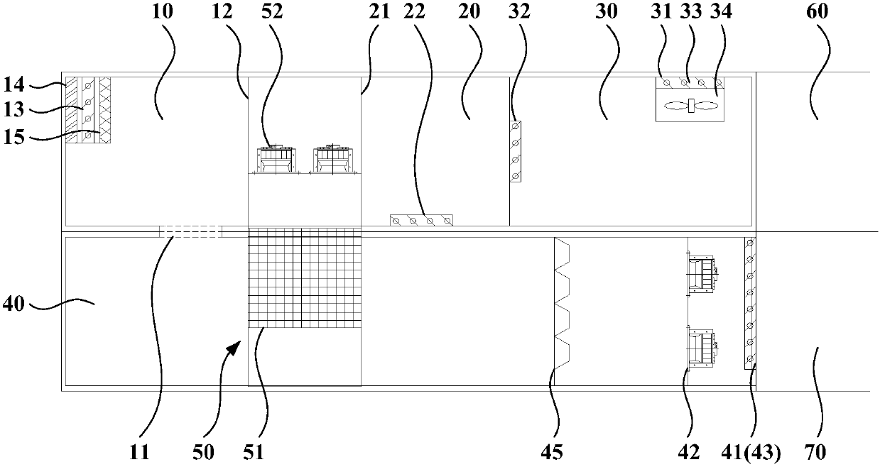
[0076] Such as image 3 As shown, the computer room air conditioning system provided by the present invention includes an air inlet chamber 10, an air mixing chamber 20, a return air chamber 30, an air supply chamber 40, an indirect refrigeration device 50, a fresh air valve 13, a first return air valve 32, a second Air return valve 22, exhaust valve 33 and blower fan 42, wherein:

[0077] The air inlet chamber 10, the air mixing chamber 20 and the return air chamber 30 are arranged in sequence and set...


PUM


Abstract

The invention discloses a computer room air conditioner system and a computer room refrigerating control method and device. The computer room air conditioner system comprises an air inlet chamber, anair mixing chamber, an air return chamber, an air feeding chamber, indirect refrigerating equipment, a fresh air valve, a first air return valve, a second air return valve, an air exhaust valve and anair feeder, wherein the air inlet chamber, the air mixing chamber and the air return chamber are arranged in sequence and are in the same layer as a computer room ceiling, and the air feeding chamberis in the same layer as a computer room body; an air vent is formed between the air inlet chamber and the air feeding chamber, a first air opening is formed in the side, close to the air mixing chamber, of the air inlet chamber, a second air opening is formed in the side, close to the air inlet chamber, of the air mixing chamber, and the indirect refrigerating equipment is arranged between the first air opening and the second air opening; the fresh air valve is arranged in a fresh air inlet of the air inlet chamber; the first air return valve is arranged between the air mixing chamber and theair return chamber, and the second air return valve is arranged between the air mixing chamber and the air feeding chamber; the air exhaust valve is arranged in the air exhaust of the air return chamber. Compared with the prior art, the air cleanness of a computer room can be improved, and the refrigerating energy consumption of the computer room can be lowered.

Description

technical field [0001] The invention relates to the technical field of refrigeration equipment, in particular to a machine room air-conditioning system, a machine room refrigeration control method and a device. Background technique [0002] A data center, commonly known as a computer room, is a complete set of complex facilities. It not only includes computer systems and other supporting equipment (such as communication and storage systems), but also includes redundant data communication connections, environmental control equipment, monitoring equipment, and various safety devices. In existing data centers, energy costs account for a relatively high proportion of computer room operating costs, and less than half of the electricity is used for IT loads, while the rest is used for infrastructure such as power supply and cooling systems. [0003] Direct fresh air cooling and indirect evaporative cooling are commonly used energy-saving operation modes for cooling equipment room...

Claims


Application Information

Patent Timeline
Patent Type & Authority Applications(China)
IPC IPC(8): F24F5/00F24F7/007F24F11/65F24F13/28F24F13/30
Inventor 张路路王锋马丽强
Owner EMERSON NETWORK POWER CO LTD
Learn More