
On-line monitoring system of high voltage DC converter valve

A high-voltage direct current, monitoring system technology, applied in the direction of measuring electricity, measuring devices, measuring electrical variables, etc., can solve the problem of DC system outage, resistance value of resistance element, capacitance value of capacitance element and other parameter deviation without real-time monitoring And other issues

Inactive Publication Date: 2018-01-30
GLOBAL ENERGY INTERCONNECTION RES INST CO LTD +2
View PDF5 Cites 23 Cited by
  • Summary
  • Abstract
  • Description
  • Claims
  • Application Information

AI Technical Summary

Problems solved by technology

[0003] The resistive and capacitive elements contained in the damping circuit and the DC voltage equalizing circuit have been operating in high voltage, strong electric field and high power environments for a long time, and are prone to aging over time. The resistance value of the resistive element, the capacitance value of the capacitive element, etc. Parameters may be offset
When the degree of parameter deviation exceeds the preset allowable range, the damping effect will fail and the voltage distribution will be uneven. In severe cases, it will cause breakdown of thyristors and even DC system shutdown.
[0004] At present, the annual maintenance method is usually used to test whether the components of the damping circuit and the DC equalizing circuit in the HVDC converter valve are normal. However, there is no technical solution for real-time monitoring, which can reduce the damage of the components and further reduce the thyristor. The thyristor trigger monitors the damage of the board and prevents the fault from expanding

Method used


Image

  • On-line monitoring system of high voltage DC converter valve
  • On-line monitoring system of high voltage DC converter valve
  • On-line monitoring system of high voltage DC converter valve

Examples


Embodiment Construction

[0037] In order to make the purpose, technical solutions and advantages of the embodiments of the present invention more clear, the technical solutions in the embodiments of the present invention will be clearly and completely described below in conjunction with the accompanying drawings in the embodiments of the present invention. Obviously, the described embodiments It is a part of embodiments of the present invention, but not all embodiments. Based on the embodiments of the present invention, all other embodiments obtained by persons of ordinary skill in the art without making creative efforts belong to the protection scope of the present invention.

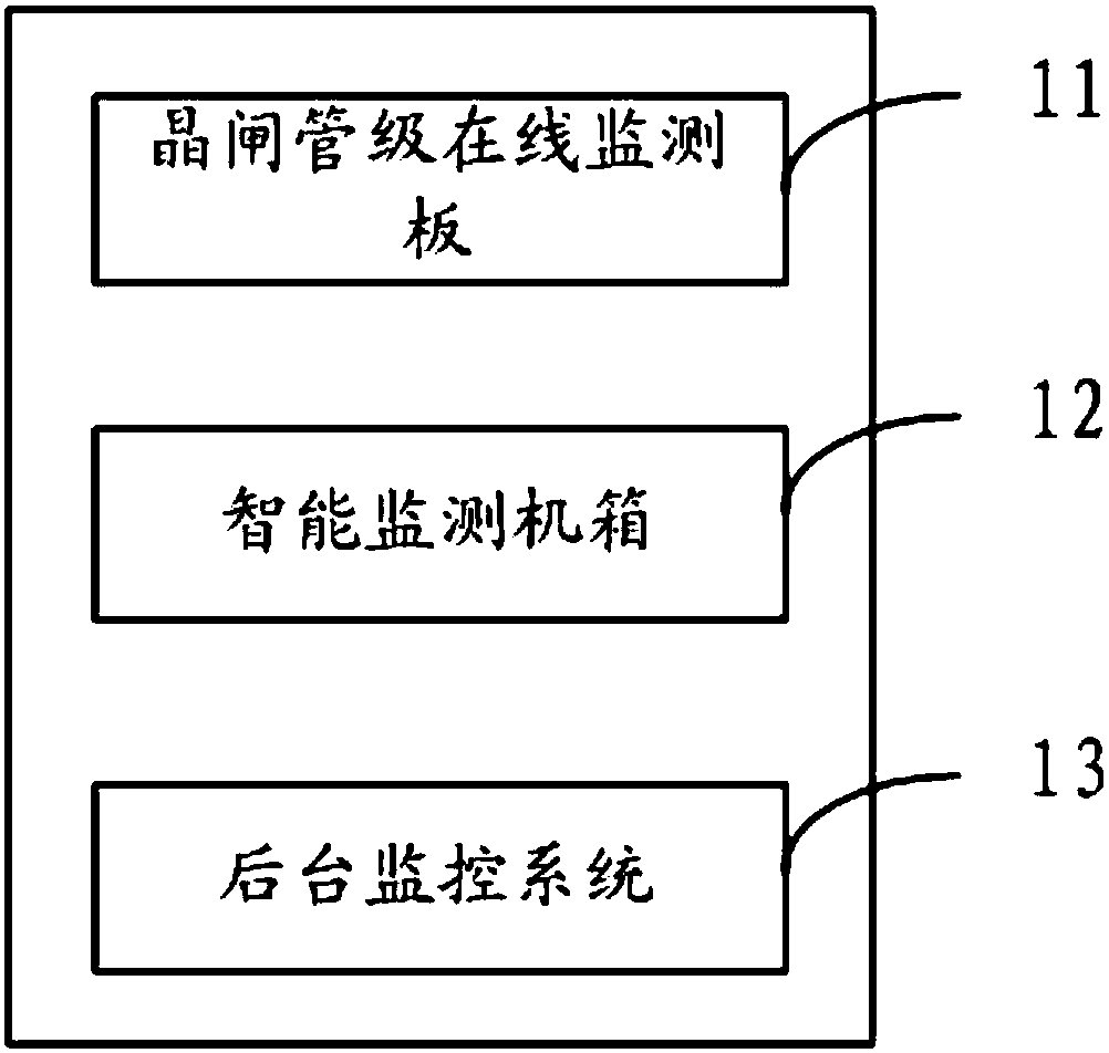
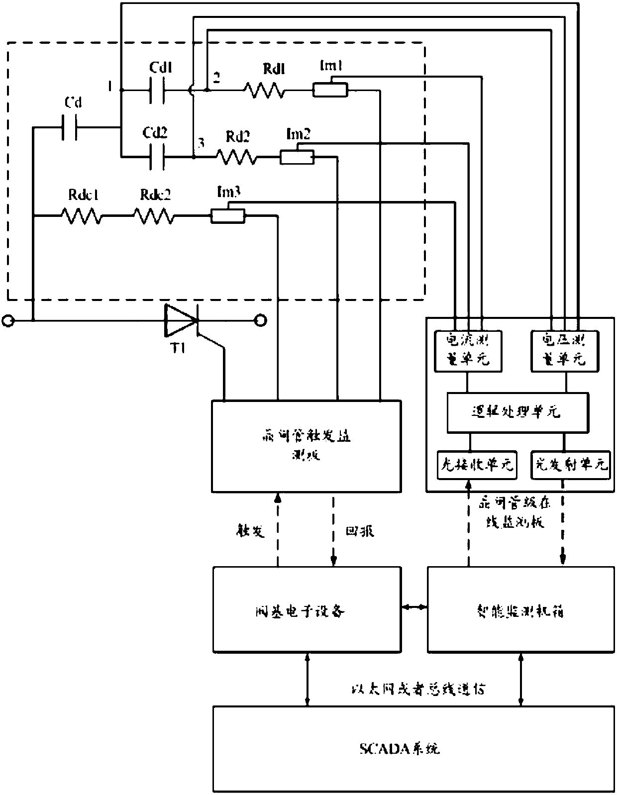
[0038] An online monitoring system for a high-voltage direct current converter valve provided by an embodiment of the present invention will be described below with reference to the accompanying drawings.

[0039] figure 2 It is a schematic diagram of an online monitoring system for a high-voltage DC converter valve in an em...


PUM


Abstract

The invention provides an on-line monitoring system of a high voltage DC converter valve, comprising a thyristor valve level on-line monitoring plate, an intelligent monitoring cabinet and a background monitoring system. The thyristor valve level on-line monitoring plate calculates the element parameters of elements contained in a damping loop and a DC voltage-sharing loop. The intelligent monitoring cabinet makes the maintenance plan of the converter valve based on the work state of the thyristor valve level and the power value transmitted by each transverter in a converter station. Comparedwith the prior art, the on-line monitoring system of a high voltage DC converter valve is advantageous in that the element parameters of elements in the thyristor valve level can be monitored in a real-time manner, and the maintenance plan of the converter valve can be made, and thereby the fault of the thyristor valve level can be found out in time and maintenance of the thyristor valve level canbe done in time.

Description

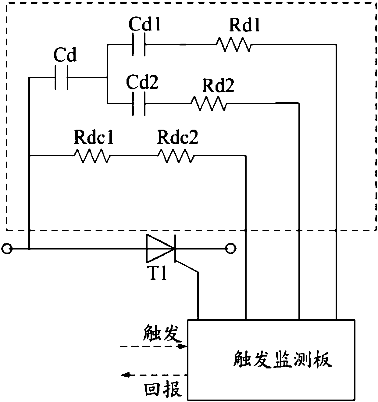
technical field [0001] The invention relates to the technical field of high-voltage direct current transmission, in particular to an online monitoring system for a high-voltage direct current converter valve. Background technique [0002] The HVDC converter valve is the key equipment of the HVDC project, and it is mainly composed of dozens of thyristors connected in series. The thyristor stage generally includes circuits such as thyristors, thyristor trigger monitoring boards, damping circuits, and DC voltage equalizing circuits. Wherein, the damping circuit is used to realize the dynamic voltage equalization function of the thyristors, and the DC voltage equalization circuit is used to realize the static voltage average distribution function among the thyristor stages connected in series. Such as figure 1 In the schematic diagram of the thyristor-level circuit shown, the damping circuit branch 1 includes capacitor Cd, capacitor Cd1 and resistor Rd1, the damping circuit br...

Claims


Application Information

Patent Timeline
IPC IPC(8): G01R31/00G01R31/26
Inventor 王华锋汤广福郝长城林志光杨树森张海峰
Owner GLOBAL ENERGY INTERCONNECTION RES INST CO LTD
Learn More