Current guide device for current transformer

A technology of current transformer and electroplating nickel, which is applied in the direction of transformer/inductor coil/winding/connection, etc., which can solve the problems of long power failure time, short power failure time, easy recurrence, etc., and achieve convenient conductive connection, prevent overheating, and increase the area Effect

Pending Publication Date: 2018-01-30
GUANGDONG POWER GRID CO LTD DONGGUAN POWER SUPPLY BUREAU
View PDF7 Cites 1 Cited by
  • Summary
  • Abstract
  • Description
  • Claims
  • Application Information

AI Technical Summary

Problems solved by technology

The current treatment method is to clean and polish the contact surface. The power outage time is short but the heating defect is easy to recur; the other is to change the structure of the connection palm or replace the current transformer with a larger carrying capacity. This method is more thorough in handling but the power outage Long time and high cost

Method used


Image

  • Current guide device for current transformer

Examples


Embodiment 1

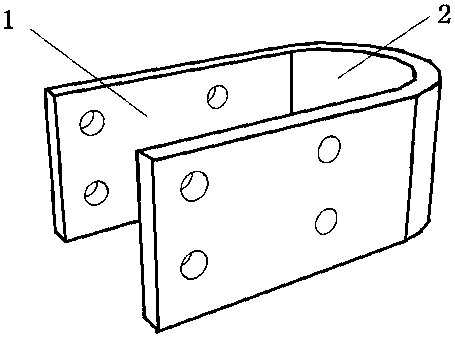
[0020] Such as figure 1 As shown, a current drainage device for a current transformer, wherein the drainage device includes a connecting part 2 and two overlapping parts 1 connected to both ends of the connecting part 2, the overlapping part 1 and the connecting part 2 form a U-shaped structure, and the overlapping The connecting part 1 is provided with 8 threaded holes, the connecting part 2 is provided with a 10mm thick copper strip, and the lapping part 1 is lapped on the wiring palm of the current transformer.

[0021] Wherein, the overlapping part 1 is fixedly connected with the terminal lug of the current transformer by inserting the bolt into the threaded hole.

[0022] Wherein, the diameters of the several threaded holes are 13mm-15mm.

[0023] Preferably, the diameter of the threaded hole is 14mm.

[0024] Among them, the inflection point radius of the U-shaped structure is 19mm-21mm.

[0025] Preferably, the radius of the inflection point of the U-shaped structure...

Embodiment 2

[0032] This embodiment is similar to Embodiment 1, the difference is that two current drainage devices are arranged oppositely on the wiring palm of the current transformer, the original current-carrying loops are increased to three, and the overlapping area is increased by 100% compared with the original one. diversion capacity.


PUM

PropertyMeasurementUnit
diameteraaaaaaaaaa
thicknessaaaaaaaaaa
lengthaaaaaaaaaa

Abstract

The invention belongs to the technical field of electric power security, and particularly relates to a current guide device for a current transformer. The current guide device comprises a connecting portion and two lapping portions connected at two ends of the connecting portion, the lapping portions and the connecting portion form a U-shaped structure, the lapping portions are provided with a plurality of threaded holes, the connecting portion is provided with a plurality of copper strips, and the lapping portions are lapped on a connection pad of the current transformer. A current-carrying loop and conductive current-carrying area are increased, and overheating of the current transformer is prevented. Moreover, without changing the structure of a connection pad of an original current transformer, the current guide device is simple and convenient to mount, and interruption maintenance time is shortened.

Description

technical field [0001] The invention belongs to the technical field of electric power safety, in particular to a current drainage device for a current transformer. Background technique [0002] The grid layout is extensive, the power supply load is large, and the connection contacts (referred to as joints or wiring palms) of power equipment current-carrying components have serious defects in heating. For outdoor current transformers, the wiring palms on both sides tend to heat up seriously, because the contact surface is severely oxidized and the current-carrying area is insufficient. The current treatment method is to clean and polish the contact surface. The power outage time is short but the heating defect is easy to recur; the other is to change the structure of the connection palm or replace the current transformer with a larger carrying capacity. This method is more thorough in handling but the power outage The time is long and the cost is high. Contents of the inve...

Claims


Application Information

Patent Timeline
Patent Type & Authority Applications(China)
IPC IPC(8): H01F27/28
Inventor 王文洪杜启业吴树平林炜蔡浩刘润权黄景生古志坚黄智刚张倩钟国华刘巨权邱林攀谢曦
Owner GUANGDONG POWER GRID CO LTD DONGGUAN POWER SUPPLY BUREAU
Why Eureka
Try Eureka